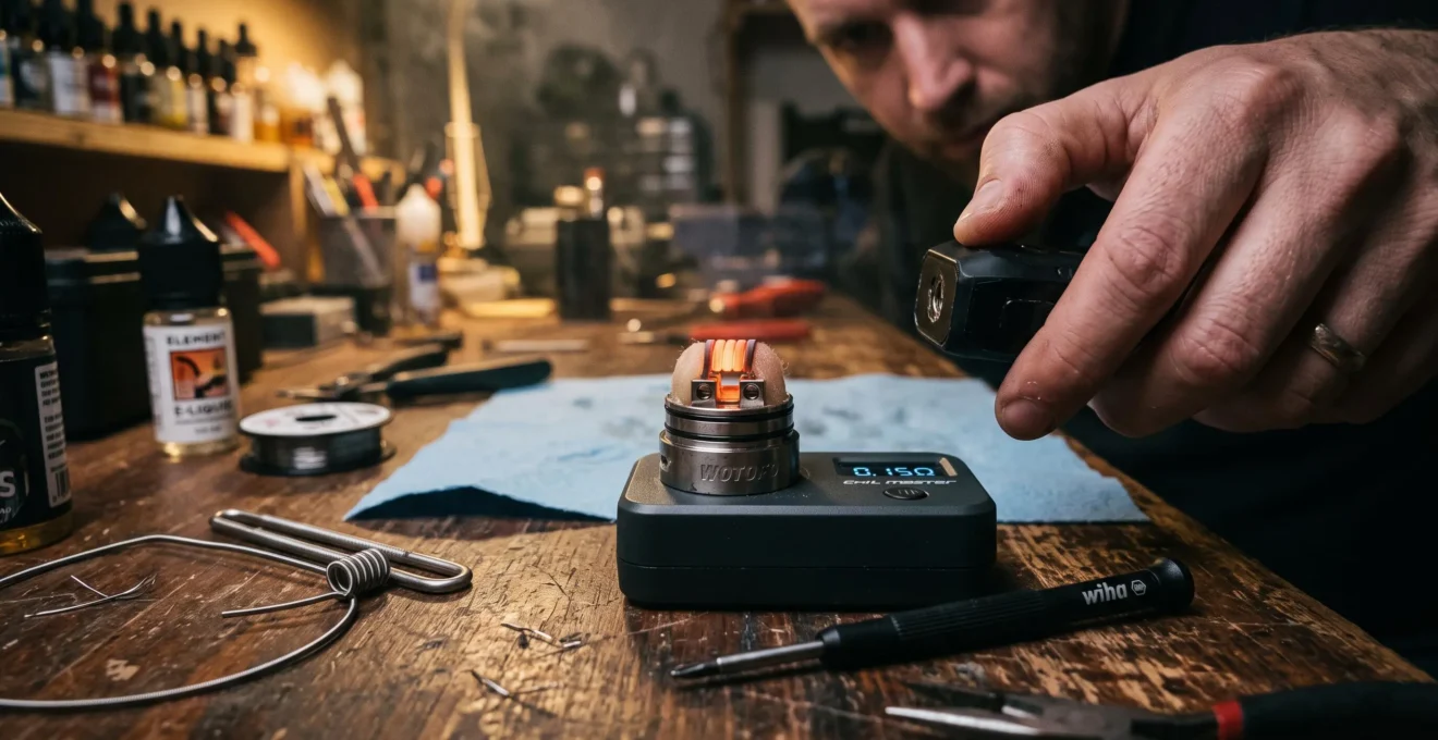
Vapour can feel smooth and flavourful on the first puff, noticeably warmer on the second, and harsh by the fourth—even when the atomiser’s power setting never changes. The difference often comes from how heat moves through the coil, wick and surrounding chamber during repeated activation.
Each puff introduces electrical energy into a heating element that may still retain heat from the previous draw. Meanwhile, the wick must replace liquid that has evaporated. If heat builds faster than liquid returns, local temperatures rise and vapour production becomes less consistent. Coil geometry, contact with the wick, airflow and the interval between puffs all influence this balance.
Understanding these interactions makes it easier to distinguish normal warming from problematic overheating. It also explains why changing wattage alone may not resolve fading flavour or an increasingly harsh draw. The most useful approach is to examine the entire heat-transfer path, from the electrical connection to the liquid being vaporised, rather than treating the coil as an isolated component.
What determines vapour consistency between puffs?
- Even heat distribution helps the wetted coil surface vaporise liquid consistently, while local hot spots can create harsh or burnt notes.
- Consecutive puffs combine residual heat with changing wick saturation, so identical power settings can produce different thermal conditions.
- Appropriate coil geometry, reliable liquid delivery, sufficient airflow and recovery time between draws help limit unwanted temperature increases.
- How Does a Metallic Heating Coil Turn Electrical Power Into Vapour?
- Why Does Uneven Heat Distribution Create Hot Spots on a Vape Coil?
- How Can Coil Spacing Improve Heat Distribution Before Wicking?
- Compact or Wide Coil: Which Spreads Heat More Evenly in Your Atomiser?
- Which Signs Show Heat Is Concentrating Too Heavily in One Part of an Atomiser?
- How Can You Reduce Heat Build-Up During Consecutive Vape Puffs?
- Which Coil Defects Can Create Hot Spots and Premature Wick Damage?
- Which Dual-Coil Installation Errors Cause One Coil to Heat Faster Than the Other?
How Does a Metallic Heating Coil Turn Electrical Power Into Vapour?
A metallic vape coil converts electrical energy into heat through resistance. That heat passes into the surrounding wick and liquid, allowing the liquid to evaporate and subsequently form an inhalable aerosol. Vapour quality depends not simply on how much power reaches the coil, but on how effectively and uniformly that energy transfers into the liquid.
When current flows through a resistive heating wire, electrical energy becomes thermal energy. The coil warms, transfers heat through direct contact with the wick, and supplies energy for liquid vaporisation. The airflow then transports the generated vapour and droplets towards the mouthpiece while removing some heat from the atomiser.
Not every watt supplied by the battery becomes useful vaporisation energy. Some energy raises the temperature of the metal and wick, some escapes into the surrounding hardware, and some is carried away by moving air. A Scientific Reports study of heat transfer and evaporation in electronic cigarette wicks examined how wick porosity, liquid composition and electrical power influence these competing processes.
Wick contact is especially important. A coil may become very hot without producing proportionately more aerosol if liquid is not reaching its surface efficiently. Poor contact leaves parts of the heating element insufficiently cooled by evaporation.
Coil thermal mass introduces another variable. More metal generally requires more energy to warm and can retain more thermal energy after activation, although resistance, geometry, airflow and material properties affect the actual response. A lightweight coil may respond rapidly to each activation, while a heavier assembly can continue warming the surrounding chamber between draws.
This distinction matters during consecutive use because neither the metal nor the liquid necessarily returns to its initial temperature before the next puff begins.
Once the heating process is understood, the next question is what happens when part of the coil transfers heat less efficiently than the rest.
Why Does Uneven Heat Distribution Create Hot Spots on a Vape Coil?
Uneven heat distribution creates hot spots when one section of a coil reaches a higher temperature than neighbouring sections. Local resistance differences, poor electrical contact or inadequate wick saturation can contribute. As liquid evaporates from the hotter area, reduced evaporative cooling may allow its temperature to rise further, increasing the likelihood of burnt flavour and wick damage.
A hot spot does not necessarily mean the entire coil is overheating. One wrap or a small contact area can operate substantially hotter than the remainder of the heating element.
In a continuous wire carrying the same current along its length, a locally higher-resistance segment can generate more heat. In other situations, resistance may be relatively uniform, but inconsistent contact with the wick leaves one section without enough liquid to absorb the energy being produced.
These differences can become more pronounced during repeated activation. A partially dry patch loses evaporative cooling, while the adjacent wetted material continues absorbing energy through liquid vaporisation.
Approximately 100°C
Temperature differences along individual coils were observed in some devices during an experimental assessment of three commercial electronic nicotine delivery systems. This is a device-specific observation, not a typical temperature difference for all atomisers.
Experimental assessment of electronic cigarette temperature-control accuracy, PLOS ONE (2018)
Uneven heating also affects flavour. Deposits can accumulate on overheated surfaces, and insufficiently wetted wick material can undergo thermal degradation. These processes may introduce unpleasant burnt notes before the entire coil or wick becomes unusable. A burnt taste, however, cannot identify the precise location or chemical cause of overheating by itself.
On a compatible, unwicked rebuildable coil, a very brief, low-power pulse can provide a qualitative visual check. Unexpected isolated glowing or a persistently brighter section may indicate an installation problem. This is a practical inspection technique rather than a scientifically validated temperature measurement. It is not appropriate for every wire material or device, and glowing a coil to high temperatures should be avoided.
For an already wicked assembly, visible glowing is not an appropriate diagnostic target. Stop using a build that produces persistent burnt notes and inspect it after allowing the atomiser to cool.
Preventing these local temperature differences starts with the geometry and installation of the heating element, before the wick is added.
How Can Coil Spacing Improve Heat Distribution Before Wicking?
Coil spacing can improve heating consistency by separating neighbouring wraps and reducing unintended electrical contact between them. Deliberate gaps make the wire layout easier to inspect and can help avoid irregular current paths in suitable rebuildable designs. However, spacing alone does not guarantee uniform temperature: coil resistance, wick contact, airflow and chamber dimensions remain equally important.
In a spaced coil, neighbouring turns are separated by visible gaps. This reduces the opportunity for adjacent wraps to touch and form unintended electrical connections. It also alters how the coil exchanges heat with its surroundings.
A contact coil behaves differently because adjacent wraps intentionally touch. Properly built contact coils can heat consistently, so touching wraps are not automatically defective. Problems arise when contact is irregular or unstable, or when the build develops an unintended hot spot.
For a compatible rebuildable setup, inspect the unwicked coil with the device disconnected from power. Confirm that the wraps are reasonably consistent, that the legs are securely mounted, and that no portion of the wire contacts the chamber or another unintended conductive surface.
Where the manufacturer permits low-power pulsing, observe whether heating develops progressively rather than concentrating abruptly at one point. Do not assume that an exact centre-outward glow pattern is mandatory for every coil design. Adjust spacing only with power disconnected, the coil cool and appropriate tools. Never manipulate an energised heating element.
Spacing introduces a geometric trade-off. Increasing the distance between wraps lengthens the completed coil, potentially moving its outer turns beyond the effective airflow area or reducing clearance inside a compact chamber.
The goal is controlled, repeatable geometry—not the widest possible spacing. Excessive gaps can reduce wick contact consistency or place some wraps where airflow is less effective.
Any spacing decision should therefore account for the atomiser’s available deck width, airflow arrangement and recommended coil dimensions. Prebuilt coil heads and sealed cartridges should not be dismantled for this procedure.
Once individual wraps are positioned correctly, the overall width and compactness of the coil determine how that heat interacts with the chamber and wick.
Compact or Wide Coil: Which Spreads Heat More Evenly in Your Atomiser?
A wider coil can distribute power over a larger active surface when its other characteristics are comparable, potentially reducing heat concentration in one area of the wick. A compact coil concentrates heating within a smaller footprint and may respond more quickly. Neither geometry is universally superior: even heating depends on how the coil fits the chamber, receives airflow and stays supplied with liquid.
The important distinction is between overall electrical power and local heat flux. Supplying similar power to different active surface areas can produce different heating conditions, although changing coil dimensions often changes resistance and thermal mass at the same time.
A compact build may suit an atomiser with a narrow chamber and concentrated airflow. Its smaller footprint can keep the heating surface aligned with the air inlet, but it may also demand effective liquid delivery through a relatively limited wick area.
A wider build can expose more liquid-contacting surface to heat. It may provide a gentler distribution of energy when appropriately powered and adequately wicked, but additional metal can change ramp-up time and retain heat between activations.
The following comparison provides a practical selection framework rather than a laboratory-validated ranking.
| Selection criterion | Compact coil | Wide coil |
|---|---|---|
| Chamber and airflow | May align more easily with narrow airflow and limited deck space. | Needs enough clearance and sufficiently distributed airflow across its active length. |
| Liquid VG ratio and wicking | Concentrates liquid demand within a smaller wick-contact region. | Needs consistent liquid supply across a longer heating surface; higher-VG liquids may refill the wick more slowly under some conditions. |
| Puff style | Can suit short activations when the overall build has low thermal mass. | May distribute heating across more wick, but thermal mass and liquid replenishment can limit repeated use. |
A mismatch can undermine either design. A wide coil installed in a chamber that directs airflow only towards its centre may leave outer wraps less effectively cooled. Conversely, a compact coil operating at high local heat flux may evaporate liquid faster than a high-VG formulation can replenish it.
VG ratio alone does not determine the correct coil width. Wick density, liquid pathways, operating power and puff duration also affect replenishment. The available research on porous wicks supports the relevance of these interactions but does not establish one ideal rebuildable geometry.
Once geometry and liquid delivery are reasonably matched, changes in flavour and wick condition can help identify whether one region still operates too hot.
Which Signs Show Heat Is Concentrating Too Heavily in One Part of an Atomiser?
Possible signs of excessive local heating include a sudden burnt or metallic flavour, increasing harshness during a session, visible wick scorching and uneven residue on the coil. A particularly useful pattern is vapour quality deteriorating after several consecutive puffs but recovering after a pause. These indicators suggest thermal or liquid-supply problems, although none independently proves a specific hot spot.
The earliest warning may be sensory rather than visual. An otherwise familiar flavour can develop a dry, sharp or burnt note after several draws, while vapour temperature and throat sensation become less comfortable.
The timing of the change provides useful context. If the first puff is normal but subsequent puffs deteriorate, the wick may be losing liquid faster than capillary action replaces it. Heat retained in the coil and surrounding metal can compound the effect.
After the device has cooled, physical inspection may reveal a darker section of cotton, a localised deposit or uneven discoloration of the heating element. These findings can help direct further examination, but deposits also depend on liquid composition and use history. Discoloration is not a precise temperature record.
A persistent burnt taste, particularly when present from the first draw, may indicate damaged wick material or a fault that requires replacement rather than further testing.
Laboratory evidence: liquid supply changes coil temperature
A 2018 PLOS ONE experiment investigated replaceable heating coils in an older top-coil clearomizer under different degrees of liquid wetness. Infrared imaging also revealed non-uniform temperature distributions along the heating elements.
With propylene glycol as the test liquid, the reported temperature ranges were 110–185°C under full-wet conditions, 145–334°C under wet-through-wick conditions and 322–1008°C under dry conditions. These values describe specific experimental conditions, including extreme dry-coil operation, and must not be treated as normal temperatures across modern atomisers.
The PLOS ONE study measuring electronic cigarette coil temperatures demonstrates the importance of liquid availability. It does not establish that every burnt sensation originates from a single section of the coil or that flavour can identify an exact operating temperature.
The most useful diagnostic is therefore a combination of observations: when the deterioration begins, whether it recovers after cooling, and whether the wick or coil shows abnormal damage.
If the symptoms mainly appear during repeated draws, the next step is to examine how power, airflow and recovery intervals affect heat accumulation.
How Can You Reduce Heat Build-Up During Consecutive Vape Puffs?
Heat build-up during consecutive puffs can be reduced by using appropriate power, allowing more time between draws, maintaining sufficient liquid supply and ensuring that airflow is unobstructed. These changes work together: lower energy input limits heating, pauses allow the coil to cool and wick liquid to replenish, and airflow removes heat during operation.
When a puff ends, electrical heating stops, but the coil, wick and surrounding atomiser do not instantly return to ambient temperature. Some stored heat remains and redistributes through the assembly.
If the next activation begins before sufficient cooling and liquid replenishment have occurred, the thermal conditions differ from those of the first draw. The same wattage can then produce a hotter or less consistently wetted heating surface.
Longer puffs increase the period of energy input, while shorter intervals reduce recovery time. Experimental research into commercial temperature-control systems has identified puff duration and intervals as relevant thermal factors, although the magnitude varies by device.
There are several practical adjustments:
- Reduce excessive power: operate within the manufacturer’s recommendations and avoid increasing wattage to compensate for fading flavour.
- Allow recovery time: lengthen the interval between puffs when vapour becomes progressively hotter or harsher.
- Check liquid delivery: confirm that the tank or reservoir contains liquid and that the wick is correctly installed and adequately saturated.
- Maintain airflow: keep the intended air inlets unobstructed, without assuming that additional airflow can compensate for a defective coil.
- Use compatible temperature control where appropriate: recognise that displayed temperature settings do not guarantee accurate or uniform coil temperatures.
Temperature control can moderate electrical input in compatible devices, but it typically relies on indirect estimates and the behaviour of a suitable coil material. Independent measurements have shown discrepancies between selected and actual temperatures in some tested systems.
To assess an adjustment, compare performance under similar conditions while changing only one setting at a time. A hypothetical example is an atomiser that delivers a normal first draw but becomes harsh during closely spaced activations. If longer pauses reduce the deterioration, insufficient recovery time is a plausible contributing factor. That observation alone cannot separate residual heat from delayed wick replenishment.
Stop the test if burnt flavour, abnormal heating or another fault appears. Repeatedly inhaling from a suspected dry or damaged wick is not necessary to diagnose it.
Five checks for more consistent thermal performance
- Record the initial configuration: note the compatible coil specification, selected power and liquid composition. The deliverable is a baseline setup record.
- Inspect the cooled atomiser: check the liquid level, visible wick condition, airflow openings and accessible connections. The deliverable is a written list of any abnormalities.
- Confirm the operating range: compare the selected power with the coil or device manufacturer’s guidance. The deliverable is a verified compatible setting.
- Change one variable: where no damage is present, adjust the puff interval or reduce excessive power without altering other settings. The deliverable is a single documented change.
- Compare the response: observe whether ordinary use remains consistent without harshness or burnt notes. The deliverable is a before-and-after observation; persistent symptoms mean discontinuing use and inspecting or replacing the affected component.
If reducing power or extending recovery intervals still leaves the first puff acceptable and later puffs harsh, investigate liquid-feed restrictions, wick placement and component condition. Repeated adjustment cannot make a physically defective build reliable.
Persistent deterioration despite reasonable settings can indicate defects in the coil or its electrical connections, particularly when the same problem appears after rebuilding.
Which Coil Defects Can Create Hot Spots and Premature Wick Damage?
Coil defects that can produce uneven heating include damaged wire, distorted wraps, inconsistent geometry and unreliable electrical connections. These faults may alter local resistance, current paths or contact with the wick. As a result, particular sections can run hotter or receive less effective cooling, increasing the risk of localised deposits and premature wick damage.
Not all defects are visible during a basic inspection. A coil can look approximately symmetrical while containing a weak connection, a deformed segment or an unintended contact between conductive surfaces.
Common issues in compatible rebuildable systems include:
- Inconsistent wrap diameter: uneven turns can create variable wick contact and airflow exposure.
- Nicks or scratches in the wire: substantial damage may reduce the effective conducting cross-section at one location.
- Poorly secured coil legs: a loose or contaminated connection can introduce additional electrical resistance and local heating.
- Deformed wraps: installation damage may create unwanted contact or leave portions of the wick less effectively heated.
- Incorrectly positioned or trimmed legs: protruding wire may touch unintended conductive surfaces, while inadequate clamping can produce unstable contact.
In the case of a nicked wire, the relevant mechanism is the change in its effective cross-section or integrity, not the mere presence of a cosmetic scratch. Similarly, a short coil leg is not automatically a high-resistance joint; poor termination or insecure contact is the underlying concern.
Some heating irregularities become apparent only when a compatible unwicked coil is tested. A brief manufacturer-permitted low-power inspection may reveal localised glowing, but it cannot identify every defect or establish the cause with certainty. Resistance readings, visual inspection and connection checks remain important.
Persistent burnt flavour after replacing the wick deserves particular attention. If the same position repeatedly develops damage, investigate coil alignment, clamping, liquid supply and airflow before attributing the problem to the liquid formulation.
A compromised coil should be replaced rather than repaired through improvised modifications. Electrical shorts, unstable resistance or damaged connections require the device to remain out of service until corrected.
There are also chemical consequences to consider. A systematic review of electronic cigarette design and aerosol toxicants, covering 92 included studies, reported associations between increased power, dry-puff conditions and higher concentrations of certain harmful aerosol constituents, including carbonyl compounds. The review did not establish that every individual coil defect produces a specific emission profile.
For a dual-coil atomiser, an additional complication arises because two separate heating elements must operate together while sharing the available electrical supply.
Key takeaways before checking a dual-coil build
- Compare the actual electrical properties of the two coils, not just their nominal specifications or appearance.
- Inspect the complete current path, including terminals and contact quality, before attributing unequal heating to coil geometry.
- Treat repeated uneven activation or unstable resistance as a build fault that needs correction before normal use resumes.
Which Dual-Coil Installation Errors Cause One Coil to Heat Faster Than the Other?
In a parallel dual-coil atomiser, each coil receives approximately the same voltage across its branch. A lower-resistance branch draws more current and dissipates more electrical power at that voltage, potentially heating differently from its partner. Unequal resistance, loose connections, mismatched geometry and inconsistent airflow or wicking can all cause one coil to reach operating temperature faster.
The electrical principle is straightforward. For a resistive branch at a given voltage, power is determined by the relationship P = V²/R. A lower resistance therefore means higher electrical power in that branch, assuming the voltage across both branches is comparable.
However, greater electrical power does not automatically mean faster temperature rise. The coil’s thermal mass, surface area, cooling and liquid contact also influence its response. Two coils may receive different power yet show similar apparent warm-up behaviour, or receive similar power while heating unevenly.
Installation errors can introduce several forms of imbalance:
- Mismatched coil specifications: two coils advertised with the same nominal resistance may differ in their actual electrical or geometric characteristics.
- Different wire or leg geometry: unequal lengths and dimensions can contribute to differences in total branch resistance and heating distribution.
- Loose or oxidised terminal contact: additional contact resistance can reduce effective power at the heating section while generating unwanted heat at the connection.
- Unequal placement: one coil positioned closer to the air inlet may receive stronger cooling than the other.
- Different wick contact: variations in wick density or saturation may cause unequal temperatures even when the electrical branches are closely matched.
A useful pre-installation check is to measure each coil individually with an appropriate resistance-measuring device, following its instructions. Closely matched values and consistent coil geometry provide a better starting point than relying on package labels alone.
When mounted, verify that the coil legs are secured correctly, screws are undamaged, and neither coil contacts the chamber or unintended conductive components. Check the total assembly resistance and compatibility with the device before powering it.
For two identical resistances connected in parallel, the combined resistance is half that of either individual coil. This theoretical relationship can help identify discrepancies, but it is not a complete diagnostic because contact resistance and measurement limitations can affect readings.
If a compatible build heats unevenly during a permitted low-power inspection, allow it to cool and investigate the slower or otherwise irregular branch. A loose connection may contribute to reduced coil heating, while positioning or wicking differences can explain a mismatch that persists despite similar electrical measurements.
Do not attempt to compensate for a faulty branch by increasing overall wattage. That can deliver excessive power to the other coil without correcting the original problem.
For the next practical check, compare each coil’s resistance and physical installation with the device disconnected, then verify that the complete assembly is electrically stable and mechanically secure. Replace damaged components and avoid using the atomiser until persistent irregularities are resolved.
Why does my vape feel warmer after several puffs at the same wattage?
Heat remaining in the coil, wick and surrounding atomiser can influence the next activation. At the same time, liquid evaporation changes wick saturation and the amount of energy absorbed through vaporisation. Shorter intervals may therefore increase warmth even without a change in electrical settings. Excessive or uncomfortable heating warrants stopping use and checking the device.
Can a coil develop a hot spot without glowing visibly?
Yes. Local temperature differences can exist below the point where metal becomes visibly incandescent. Liquid saturation, airflow and electrical contact may create thermal imbalances without an obvious visible glow. The absence of glowing does not prove that a coil is heating uniformly, and glowing a wicked coil is not an appropriate test.
Does temperature-control mode prevent burnt or dry puffs?
Not reliably in every situation. Compatible temperature-control systems can reduce electrical power in response to estimated coil-temperature changes, but their accuracy depends on device implementation, coil material and operating conditions. Laboratory measurements have identified substantial discrepancies between selected and measured temperatures in some products. Temperature control cannot correct insufficient liquid supply or a damaged wick.
Does a higher-VG e-liquid always make the coil run hotter?
No. VG-rich liquids may flow and replenish particular wicks differently from PG-rich mixtures, but operating temperature also depends on power, wick structure, airflow and the rate of evaporation. Research on porous-wick heat transfer confirms that liquid composition interacts with other variables. VG percentage alone cannot predict whether an atomiser will overheat during consecutive use.
Can lowering wattage fix a repeatedly burnt wick?
Reducing excessive power can lower heating demand, but it cannot restore damaged wick material or repair defective connections. If burnt flavour continues at an appropriate setting, discontinue use and inspect the coil, wick and liquid delivery system after cooling. Replace compromised components instead of repeatedly testing them through inhalation.