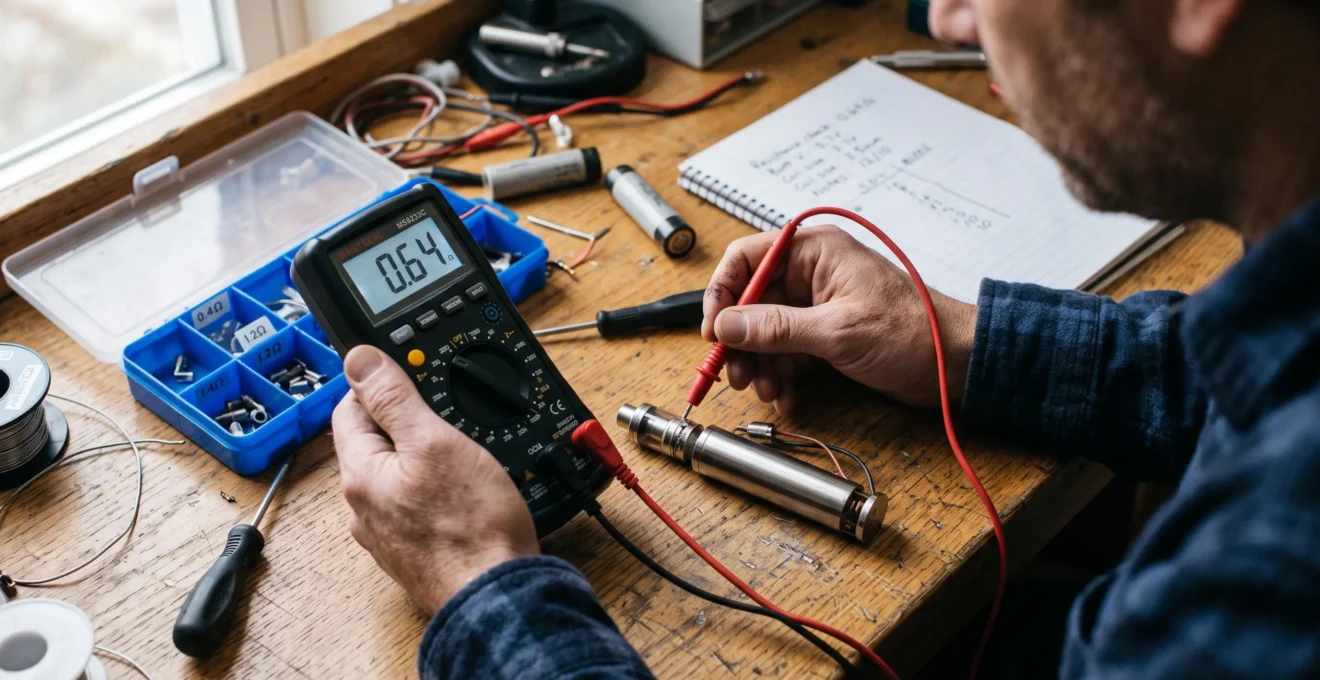
A vape device converts electrical energy stored in a battery into heat through a resistive coil. Understanding that process requires more than recognising the numbers on a screen: voltage determines the electrical potential applied to the coil, resistance influences current flow, and power describes how quickly electrical energy is converted into heat.
The essential relationships are Ohm’s law, I = V/R, and the electrical power equation, P = V × I. Their interpretation depends on the device’s architecture. An unregulated device exposes its coil to battery voltage, subject to losses, while a regulated device uses electronic circuitry to control the output.
Battery configuration, contact resistance, coil geometry and operating limits also affect what happens when the firing button is pressed. These principles explain why two devices with similar resistance readings can place different demands on their batteries or produce different heating behaviour.
The goal is to understand the electrical system, interpret measurements accurately and recognise conditions that require attention rather than assuming a displayed wattage guarantees safe operation.
Vape circuit fundamentals at a glance
- Voltage, current and resistance are linked: changing one affects the others according to Ohm’s law and the operating conditions.
- Regulated and unregulated devices behave differently: electronic power regulation separates the coil’s output conditions from the battery’s instantaneous voltage.
- Battery and coil limits matter: safe electrical interpretation requires checking current, resistance, cell characteristics and device protections together.
- Why Are Voltage, Current and Resistance Linked in a Vape Circuit?
- How Can You Trace the Electrical Path Through a Basic Vape Circuit?
- Series or Parallel Circuits: What Changes Electrically in Multi-Cell Devices?
- Which Circuit Misconceptions Can Lead to Wrong Assumptions About Vape Power?
- In What Order Should You Learn Vape Circuit Basics Before Studying Advanced Electronics?
- Why Does Lower Coil Resistance Change Electrical Demand in a Vape?
- How Is Power Delivered to a Vape Coil When Resistance Changes?
- How Does Electrical Resistance Affect Power and Heating in a Vape Coil?
Why Are Voltage, Current and Resistance Linked in a Vape Circuit?
Voltage, current and resistance are linked because the voltage across a resistive coil determines how much current flows through it. Ohm’s law expresses this relationship as I = V/R. In an unregulated vape, available battery voltage largely determines coil current. In a regulated device, electronic circuitry adjusts the output, changing how the same relationship appears in practice.
The three quantities describe different electrical properties:
- Voltage (V): the potential difference across the coil, measured in volts.
- Current (I): the rate of electric charge flow, measured in amperes.
- Resistance (R): the opposition to current flow, measured in ohms (Ω).
As explained in OpenStax‘s explanation of Ohm’s law and simple circuits, the relationship applies to ohmic loads under the relevant conditions. A coil’s resistance can also vary with temperature, so a displayed resistance may not remain constant during heating.
In a mechanical device, the battery connects to the coil through a conductive path. The voltage actually reaching the coil is affected by cell voltage, internal resistance and contact losses. Lower coil resistance generally increases current demand if the applied voltage remains approximately unchanged.
A regulated device introduces an important distinction. Its controller uses battery energy to establish a separate coil-output voltage and current, subject to conversion and operating limits.
For a hypothetical 0.50 Ω coil receiving 20 W, the equations give:
- P = V × I
- P = V²/R
- V = √(P × R) = √10 ≈ 3.16 V
- I = √(P/R) = √40 ≈ 6.32 A
These are coil-side values, not necessarily the battery’s voltage or current. Battery-side current also depends on the controller’s efficiency and the battery’s input voltage.
At constant power, decreasing resistance produces lower required output voltage but higher coil current. At constant voltage, decreasing resistance increases both current and power. This difference explains why identical coils can behave differently across device architectures.
The equations become considerably more useful once each electrical quantity can be located within the physical circuit.
How Can You Trace the Electrical Path Through a Basic Vape Circuit?
A basic vape circuit contains an energy source, conductive connections, a switching mechanism, a heating coil and a return path. In regulated devices, a controller sits between the battery and coil to manage electrical delivery. Tracing those elements reveals where power is converted, how firing is controlled and which components can interrupt operation when a fault occurs.
A simplified regulated-device functional sequence is:
- Battery cell or cells: provide the electrical energy available to the device.
- Battery terminals and conductors: connect the cells to the control electronics.
- Control board: measures relevant conditions and regulates power delivered to the atomizer.
- Firing switch: communicates the user’s request to activate the output.
- Power-switching circuitry: uses electronic components such as MOSFETs to control the higher-current electrical path.
- 510 connector and coil: transfer electrical output to the resistive heating element.
- Return conductor: completes the electrical circuit.
This is a functional description, not a universal physical wiring order. In particular, the firing button on a regulated device is commonly part of a low-current control circuit rather than being directly in series with the coil.
The distinction is documented in Evolv DNA 75C technical specifications. The manufacturer describes its module as a regulated DC-DC converter whose internal transistor circuitry handles power switching while the firing switch performs a logic function.
The same documentation identifies battery monitoring, reverse-polarity protection and error conditions including No Atomizer, Check Atomizer, Check Battery and Shorted. Depending on the fault, the controller may prevent firing or operate below the requested wattage.
Protection is not limited to the chip. Battery-wrap integrity helps prevent unintended electrical contact, while appropriate venting paths are intended to provide an escape route for gases if a cell fails. Venting does not prevent failure or make an unsafe cell acceptable.
A non-invasive diagnosis can follow the circuit logically: check the device’s reported battery condition, inspect accessible contacts for visible damage, examine the displayed coil-resistance reading and note any warning message. Avoid bypassing protections or probing a powered device’s internal circuitry.
Once the energy path is understood, the next distinction is how multiple battery cells alter the electrical conditions entering that path.
Series or Parallel Circuits: What Changes Electrically in Multi-Cell Devices?
Series connections increase total battery voltage, while parallel connections increase available ampere-hour capacity without substantially changing nominal pack voltage. These configurations also affect individual-cell current and battery-management requirements. In a regulated device, however, the controller and the requested output power determine actual battery demand, so battery arrangement alone cannot establish how safely a device operates.
The differences become clearer when comparing equivalent cell arrangements.
| Electrical property | Series | Parallel |
|---|---|---|
| Pack voltage | Individual cell voltages add together. | Approximately equal to one cell’s voltage. |
| Capacity in ampere-hours | Approximately that of one cell for identical cells. | Individual capacities add together. |
| Cell current | The same current flows through each cell in the series path. | Total current is shared between branches, not necessarily equally. |
| Main electrical concern | Cell imbalance and unequal discharge characteristics. | Unequal current sharing and unwanted equalisation currents. |
| Controller implications | Higher input voltage can reduce input current for a given power. | Lower input voltage can require greater aggregate input current. |
For an explicitly hypothetical example, two identical 3.6 V nominal, 2,500 mAh cells would provide approximately 7.2 V nominal and 2,500 mAh when connected in series. In parallel, they would provide approximately 3.6 V nominal and 5,000 mAh. These figures illustrate configuration arithmetic, not recommended cells or a device-building procedure.
Higher series-pack voltage can lower the current required for the same input power. This may reduce conduction losses in some circuitry, although actual converter efficiency depends on the controller design and operating conditions.
Parallel arrangements distribute demand across cells, but differences in internal resistance, state of charge and connection resistance can cause unequal sharing.
As Battery University‘s article on series and parallel battery configurations explains, cell matching and imbalance are important considerations in multi-cell systems.
Series configurations require particular attention because the same current passes through every cell while their individual voltages can diverge. A weaker cell may reach a discharge limit earlier. Parallel cells must also be appropriately matched, particularly in voltage, before being connected, because voltage differences can drive unwanted equalisation currents.
Identical external battery-bay layouts do not establish whether a device uses series or parallel wiring. The configuration should be determined from reliable manufacturer documentation rather than the visible orientation of the cells.
For removable-cell devices, appropriate matching practices include following the manufacturer’s cell specifications, keeping designated cell sets together where required and not combining cells with different histories or conditions. Matching does not eliminate all battery-related risks.
These distinctions also expose several persistent misconceptions about power, battery capacity and what the numbers on a device display actually represent.
Which Circuit Misconceptions Can Lead to Wrong Assumptions About Vape Power?
The most consequential misconceptions arise from applying a correct electrical formula under the wrong conditions. Lower resistance does not always mean higher delivered power, a battery’s milliamp-hour rating does not establish its discharge capability, and displayed wattage does not reveal the entire electrical demand. Each claim must be evaluated against the device architecture, coil characteristics and controller limits.
One common assertion is that lower resistance always produces more power. For a fixed voltage across a resistive coil, P = V²/R supports that conclusion. In wattage-regulated operation, however, the controller can reduce output voltage as resistance decreases while maintaining approximately the same selected power.
A second misunderstanding treats declining battery charge as a direct reduction in coil power. An unregulated setup generally delivers less power as cell voltage declines, other conditions being equal. A regulated converter may maintain its output by drawing more input current as battery voltage falls, until an operating limit intervenes.
Battery capacity is also frequently confused with current capability:
- mAh describes electrical charge capacity.
- A describes electric current.
- Continuous discharge rating describes a specified continuous current capability under stated conditions.
- W describes the rate of energy transfer or conversion.
Another misconception equates equal wattage with equal coil temperature. Coil mass, material, surface area, liquid supply and airflow influence the resulting thermal behaviour. Two coils operating at the same wattage can warm at different rates and transfer heat differently.
A practical way to evaluate community-sourced electrical advice is to identify the units, establish whether the claim concerns battery input or coil output, check whether voltage or wattage is being held constant, and compare the result with documented equipment limits.
Numerical plausibility alone does not establish safety. Incorrect cell ratings, damaged battery insulation or unsuitable device configurations cannot be validated simply by obtaining a plausible answer from Ohm’s law.
Avoiding these interpretation errors is a necessary foundation before studying higher-demand circuits or more complex control systems.
In What Order Should You Learn Vape Circuit Basics Before Studying Advanced Electronics?
Vape circuit fundamentals are best learned in an order that moves from electrical quantities to complete systems. Begin with Ohm’s law and power, then trace the circuit, study battery discharge behaviour, compare multi-cell arrangements and finally examine regulation. Each stage supplies the concepts needed to interpret the next without confusing component-level measurements with whole-device behaviour.
A useful five-stage learning sequence is:
- Voltage, current, resistance and power: understand their units and equations before interpreting screen readings.
- Circuit continuity and components: identify the energy source, conductors, switching electronics, resistive load and return path.
- Cell behaviour: distinguish capacity, continuous discharge rating, C-rate, internal resistance and voltage sag under load.
- Multi-cell arrangements: understand series voltage addition, parallel current sharing and the consequences of cell imbalance.
- Electronic regulation: distinguish battery input from coil output and learn how operating limits affect power delivery.
For each stage, understanding should be demonstrated rather than assumed. After studying the power equations, for example, a reader should be able to predict theoretical output voltage from a stated wattage and resistance, then recognise why a real device might show a different measured value.
C-rate can be introduced as a discharge-current relationship to rated capacity. It is not a substitute for a verified continuous discharge rating, particularly when evaluating removable lithium-ion cells.
Before progressing toward rebuildable atomizers or unregulated devices, readers should be able to calculate current under the relevant circuit conditions, distinguish cell current from coil current and identify the applicable continuous discharge and device limits.
These topics should not be treated as a checklist granting automatic permission to operate a potentially hazardous configuration.
Five checks to confirm your circuit knowledge
- Write down the four electrical quantities—voltage, current, resistance and power—with their correct units; produce a four-entry reference table.
- Calculate theoretical voltage and current for a clearly labelled hypothetical resistance and power setting; retain both equations and results.
- Sketch a functional regulated-device circuit identifying the battery, controller, switch signal, coil and return path; label battery input and coil output separately.
- Prepare a series-versus-parallel comparison showing pack voltage, capacity and current-sharing principles for identical hypothetical cells; label the assumptions.
- Read a manufacturer’s documented operating specifications and identify its voltage, current, resistance and battery-related limits; produce a short limits checklist without applying it to an undocumented configuration.
The exercise is complete only when its results can be explained in terms of the relevant circuit. An equation without its operating assumptions is not a sufficient safety check.
With the foundations established, lower coil resistance can be examined in greater detail, including what it changes electrically and what it does not.
Why Does Lower Coil Resistance Change Electrical Demand in a Vape?
Lower coil resistance increases current demand when voltage across the coil remains constant. This follows directly from I = V/R. In a regulated device operating at constant wattage, lower resistance instead requires higher coil-output current and lower coil-output voltage. The effect on battery current is different because it also depends on the requested power, battery voltage and conversion efficiency.
Consider two hypothetical resistive coils operating at the same 3 V output.
A 1.0 Ω coil draws 3 A and dissipates 9 W. A 0.5 Ω coil draws 6 A and dissipates 18 W. Halving the resistance doubles current and power under the stated constant-voltage conditions.
Now consider the same two resistances at a constant 18 W output. From I = √(P/R), the 1.0 Ω coil requires approximately 4.24 A, whereas the 0.5 Ω coil requires 6 A. The necessary output voltages are approximately 4.24 V and 3 V, respectively.
These calculations describe the resistive load. They do not establish that either configuration is compatible with a particular battery or device.
Coil construction adds a physical dimension to the relationship. Wire material, thickness, effective conductor length and geometry influence resistance. Wire gauge and number of wraps can change conductor length and mass, while coil shape and surface area affect heat distribution.
A more massive coil can take longer to heat at the same supplied power because more thermal energy is needed to raise its temperature, although heat loss and liquid contact also matter.
In a regulated device, the controller may encounter an output-current limit or a minimum supported resistance as coil resistance decreases. The result may be reduced available wattage or a fault indication, depending on the model.
Checking electrical demand therefore requires two separate assessments: calculating coil-output conditions and evaluating battery-input demand against verified device and cell specifications. Directly comparing regulated coil-output current with a battery’s continuous discharge rating would confuse two different parts of the circuit.
The next question is how the regulation circuitry produces the required output as coil resistance or available battery voltage changes.
How Is Power Delivered to a Vape Coil When Resistance Changes?
Power reaches a vape coil when electrical current passes through its resistance and converts electrical energy into heat. In an unregulated circuit, the applied battery voltage largely determines the resulting power. A wattage-regulated device instead adjusts its coil-output voltage and current to approach the selected power, provided its operating limits and available battery energy permit it.
The relationship P = V²/R describes power in a resistive coil. How the device responds to resistance changes depends on the electrical quantity being controlled.
Under approximately constant-voltage operation, a reduction in resistance increases current and power. If battery voltage declines during discharge, delivered power generally falls as well.
Under constant-power regulation, the controller monitors relevant output conditions and changes its electrical conversion behaviour. When resistance decreases, the output voltage required for the same wattage decreases while output current rises.
The coil is therefore part of a controlled power-delivery system rather than a load connected directly to an unchanged battery voltage.
This compensation has boundaries. A controller can have minimum supported resistance, maximum output voltage, maximum output current and battery-input limits. Thermal protection and cell-voltage monitoring may impose additional constraints.
The DNA 75C module, for example, is specified by its manufacturer for 1–75 W output, 0.2–9.0 V output voltage and 0.5–30.0 A continuous output current. These are component-specific specifications, not universal limits for regulated vape devices.
Its documentation also reports a typical conversion efficiency of 85 %. That figure is a manufacturer-stated operating characteristic, not a fixed efficiency applicable to all devices or every operating point.
The controller may be unable to reach the requested wattage if an output or battery limit is reached. Its response can include reduced power delivery, a warning or an inhibited firing operation, depending on the condition.
From a thermal perspective, controlled power can make heating more consistent across a battery discharge cycle. It cannot guarantee identical temperature behaviour across coils with different materials, mass, geometry or liquid contact.
The remaining step is to connect these electrical relationships with the actual heating process inside the coil.
Key takeaways before examining coil heating
- Electrical power specifies the rate of energy conversion, but coil geometry determines how that energy is distributed.
- A changing resistance reading can reflect temperature-dependent material behaviour or an electrical fault; context determines its meaning.
- Interpreting coil heating requires separating normal temperature effects from unstable connections, shorts and interruptions.
How Does Electrical Resistance Affect Power and Heating in a Vape Coil?
Electrical resistance determines how current and voltage combine to produce heat in a coil. Through Joule heating, electrical energy is converted into thermal energy at a rate described by P = I²R. However, resistance alone cannot predict coil temperature or vaporisation behaviour because material, surface area, thermal mass, airflow and liquid contact also control heat transfer.
The coil is deliberately constructed as a resistive heating element. Under normal operation, a substantial portion of the electrical energy delivered to the atomizer is converted into heat in this element.
For a given current, higher resistance produces greater heating power according to P = I²R. For a given applied voltage, the relationship is P = V²/R, so lower resistance produces greater power. At fixed power, resistance determines the necessary voltage-current combination but not the total electrical energy delivered per unit time.
These different conditions explain why apparently contradictory resistance claims can each be mathematically correct within their assumptions.
Coil geometry matters because the same total power can be distributed across different wire lengths and surface areas. A comparatively large heating surface may distribute energy differently from a smaller one, while thermal mass influences how rapidly temperature changes.
Heat flux—power distributed over heating surface area—provides additional context, although it cannot independently predict operating temperature because heat is also transferred to liquid, air and surrounding components.
Temperature-dependent resistance adds another function. Certain compatible wire materials exhibit measurable resistance changes as temperature rises. A temperature-control chipset can use that behaviour to estimate coil temperature when the material properties and reference resistance are appropriately established.
That estimate has limitations. Poor electrical contacts, unstable resistance readings or incorrect material settings can undermine accuracy.
Resistance also provides diagnostic information:
- Unexpectedly low resistance: may indicate unintended electrical contact or a short circuit.
- Open-circuit or unusually high readings: may indicate a broken heating element or an interrupted connection.
- Unstable readings: may indicate contact problems, connection movement or other faults.
- Localised hot spots: may result from uneven current paths, poor coil geometry or uneven heat transfer, requiring appropriate inspection rather than continued operation.
Some resistance movement with temperature is normal for particular materials. The concern is whether the reading is consistent with the material, device operating mode and documented specifications.
A device reporting a short circuit, abnormal resistance or a recurring atomizer fault should not be forced to fire. It is safer to stop using the affected equipment until the cause has been identified through manufacturer-approved checks or competent servicing.
A practical next step is to compare a device’s documented limits with its displayed electrical measurements, keeping battery input and coil output separate. That approach turns circuit theory into a reliable method for understanding hardware behaviour without treating calculated power as proof of electrical or battery safety.
Does a vape coil’s resistance stay constant while it heats?
Not necessarily. Electrical resistance can change with temperature, depending on the conductor material. Temperature-control electronics can use suitable resistance changes to estimate coil temperature. A changing reading must therefore be interpreted alongside material properties, connection stability and the device’s operating mode.
Why can battery current be different from the current flowing through the coil?
A regulated device uses power-conversion circuitry between its battery and heating coil. Battery-side and coil-side voltage can differ, so their currents can differ too. The approximate energy relationship is battery input power multiplied by conversion efficiency equals coil output power, with actual behaviour depending on the controller and operating conditions.
Can a resistance measurement alone establish whether a vape configuration is safe?
No. Resistance is only one variable. Evaluating electrical compatibility also requires knowledge of the device architecture, battery condition, verified continuous discharge capability, wiring configuration and controller limits. A resistance reading cannot detect every fault or establish that an arrangement is safe.
What is voltage sag in a vape battery?
Voltage sag is the reduction in a cell’s terminal voltage when it supplies electrical current. It is influenced by factors including internal resistance, current demand, temperature and cell condition. In a regulated device, the controller may compensate for declining input voltage within its operating range, but battery-related protection limits still apply.
Why might a regulated device deliver less wattage than its selected setting?
The requested power may require an output voltage or current beyond the controller’s permitted range, or the battery may be unable to satisfy the input requirements. Some devices reduce achievable power under these conditions, while others display an error or inhibit firing. The applicable behaviour depends on the manufacturer’s design and specifications.