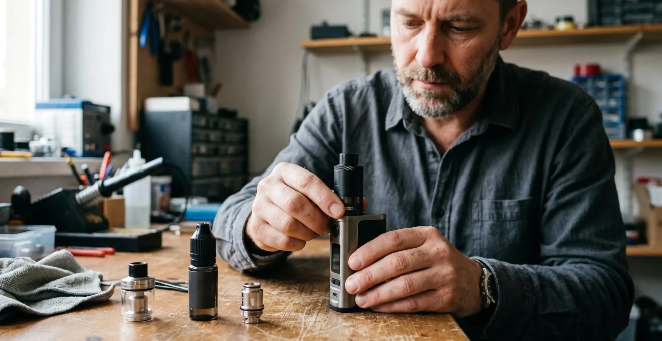
Airflow dynamics determine how much effort a vape requires to inhale, how effectively its heating element loses heat and how the resulting aerosol travels through the atomiser. Restricting an air inlet generally increases draw resistance and reduces cooling airflow. Opening it allows greater air throughput, although the effect on vapour production depends on coil power, liquid supply and internal geometry.
These relationships explain why two atomisers operating at similar wattages can feel entirely different. Air must pass through the inlet, move around or through the heating element, carry evaporated e-liquid into a cooling region and exit through the chimney and mouthpiece. Each stage introduces resistance and influences temperature, mixing and condensation.
Understanding those stages makes airflow adjustment more predictable. Rather than treating a warmer draw, weaker flavour or inconsistent cloud as an isolated symptom, the useful question is which part of the air path is limiting the system and whether the coil and wick can support the chosen operating conditions.
Vape airflow dynamics at a glance
- Closing airflow generally increases inhalation resistance and can raise aerosol temperature by reducing convective cooling.
- Vapour output depends on airflow, heating power and e-liquid replenishment; more airflow does not always produce more aerosol.
- Inlet position, coil alignment, chimney geometry and wick condition must work together for a consistent draw.
- Why Does Closing Vape Airflow Often Make the Draw Feel Warmer and Tighter?
- How Can You Tune Vape Airflow Without Losing Flavour or Overheating the Coil?
- Bottom, Side or Top Airflow: Which Layout Changes the Draw Most?
- Which Airflow Problems Cause Whistling, Turbulence or an Uneven Draw?
- How Can Coil Position Improve Airflow Efficiency Inside a Rebuildable Atomiser?
- How Can Airflow Position Determine the Most Effective Coil Configuration?
- Narrow or Wide Vape Chimney: Which Better Suits a Restricted or Airy Draw?
- When Does High-Volume Airflow Make Sense in a Vape Setup?
Why Does Closing Vape Airflow Often Make the Draw Feel Warmer and Tighter?
Closing vape airflow makes the draw tighter because a smaller opening creates greater resistance to incoming air. It often makes the aerosol feel warmer because less air passes through the heated region to carry heat away. However, the resulting temperature depends on power, puff duration and atomiser design; both aerosol and coil temperatures may change.
Airflow restriction changes two related quantities: the volume of air entering during a puff and the pressure difference needed to move that air. At a comparable inhalation effort, a narrower inlet normally permits less flow. Maintaining a similar flow through the smaller opening requires greater suction.
This distinction matters when diagnosing a restrictive draw. Mechanical restriction describes the physical narrowing of an air passage, whereas pressure drop describes the measurable resistance encountered as air travels through the complete device. The airflow ring, chimney and drip tip can all contribute, even when only one is adjustable.
Experimental research published in Nicotine & Tobacco Research measured differences in pressure drop, airflow and aerosol production between electronic cigarette devices. Air-hole area correlated with pressure drop in some products, demonstrating that inlet geometry can influence draw resistance without establishing one universal relationship for every atomiser. The findings are accessible through the PubMed record of the electronic cigarette airflow and pressure-drop study.
Temperature introduces another variable. With reduced incoming airflow, there may be less convective heat removal from the heating assembly and less cool air available for mixing with the forming aerosol. The mouthpiece can consequently deliver a warmer sensation. It would nevertheless be incorrect to assume that only the aerosol warms while coil temperature remains unchanged.
A smaller, warmer aerosol stream may taste more intense without representing greater total aerosol production. Sensory concentration, aerosol mass and visible cloud size are different measures. Depending on the equipment, excessive restriction can reduce effective vapour transport or allow the wick to become overheated.
Closing the airflow to compensate for weak flavour is therefore not necessarily a solution. On a high-power sub-ohm device, insufficient cooling combined with inadequate liquid replenishment may increase the risk of overheated or dry wick conditions.
Once restriction and temperature are treated as separate variables, airflow can be adjusted methodically rather than by repeatedly closing the inlet until the draw becomes uncomfortable.
How Can You Tune Vape Airflow Without Losing Flavour or Overheating the Coil?
To tune vape airflow, begin with an adequately open inlet within the atomiser manufacturer’s recommended operating range. Reduce the opening gradually while keeping other settings consistent, then assess temperature, flavour and draw resistance. If the aerosol becomes uncomfortably hot or harsh, restore airflow and reassess power rather than continuing to increase restriction.
Starting open provides a useful reference point. It makes changes in inhalation resistance easier to identify and reduces the likelihood of beginning with an excessively restrictive setting. This is a practical troubleshooting approach, not a scientifically established universal sequence.
Airflow and wattage should be considered together because electrical power supplies heat while the moving air and evaporating liquid help remove it. Reducing airflow without changing power can alter the heating element’s operating temperature, but the magnitude varies between devices.
Laboratory measurements in a PLOS ONE study on electronic cigarette temperature control found that average and maximum aerosol temperatures decreased as airflow increased in the systems tested. The researchers evaluated airflow conditions including 0, 25 and 55 mL/s. These findings establish an experimentally observed cooling effect, not a fixed wattage correction applicable to every atomiser.
When a tighter draw produces uncomfortable heat, a modest power reduction within the manufacturer’s specified range may help restore the balance. Stop using the device if a burnt taste develops; additional airflow alone cannot repair damaged wick material.
Flavour changes require careful interpretation. An airy draw may seem less concentrated because aerosol is mixed with more incoming air. Conversely, strong restriction may produce an intense but uncomfortable sensation, especially when heating exceeds liquid replenishment.
Harshness does not by itself prove coil overheating: liquid formulation, nicotine concentration and coil condition can also influence the sensation. Likewise, weak flavour with relatively cool aerosol may reflect a worn coil, inadequate liquid delivery or a particular air path rather than an airflow setting alone.
Five checks for a controlled airflow adjustment
- Confirm that the installed coil, device power and e-liquid are compatible with manufacturer guidance; record the initial settings.
- Open the airflow to an appropriate starting position and take a normal reference puff; note draw effort, temperature and flavour.
- Reduce the airflow by one small increment and repeat under comparable conditions; record whether the change improves the experience.
- Check for excessive heat, harshness or declining flavour; document the first setting that produces an undesirable symptom and return to a comfortable setting.
- After allowing the coil adequate time to replenish liquid, compare several normal puffs and retain the setting that remains consistent without overheating.
For a more informative diagnosis, change only one variable at a time. Altering wattage, airflow and puff duration simultaneously makes the cause of any improvement difficult to identify.
If an appropriate setting remains difficult to find, the atomiser’s internal airflow layout may be more influential than the position of its external adjustment ring.
Bottom, Side or Top Airflow: Which Layout Changes the Draw Most?
Bottom, side and top airflow layouts change the direction air takes toward the coil, but none automatically creates the tightest or airiest draw. Bottom-fed designs introduce air beneath the heating element, side-fed designs direct it laterally, and top-inlet designs route it through upper passages. Actual resistance depends on opening dimensions, internal turns and the complete air path.
With bottom airflow, air typically rises into the coil region from below. This can expose the underside of the heating element directly to incoming air, making the arrangement suitable for designs that need substantial airflow through the heating zone. Its cooling performance depends on the size and placement of the outlet beneath the coil.
Side airflow directs air across the coil from one or more lateral openings. It can suit horizontal builds where the moving air reaches a large part of the heated surface. The relationship between inlet height, coil diameter and chamber geometry affects how evenly the stream travels across the assembly.
Top airflow requires particular care in terminology. An atomiser may take air in through openings near its top while internal channels redirect that air downward and then upward through the coil region. A top-mounted inlet therefore does not necessarily mean that air approaches the coil from above.
Similarly, a shortened vapour path does not automatically result from top airflow, nor is greater flavour intensity guaranteed by a particular inlet location.
The differences become clearer when practical handling is included in the comparison.
| Layout | Air path and potential advantage | Practical limitation |
|---|---|---|
| Bottom airflow | Often directs air upward onto the coil, supporting direct exposure of its lower surface. | Liquid entering the lower air channel may cause gurgling or leakage. |
| Side airflow | Directs air laterally across a coil and can suit horizontal configurations. | External openings may be obstructed by a user’s grip. |
| Top airflow | Places external openings higher on the assembly and can use redirected internal channels. | Longer or more complex passages may introduce additional flow resistance. |
Inlet-to-coil distance is as important as the external opening’s location. Air approaching from a distant side channel may behave differently from a concentrated jet aimed directly at the coil, even though both atomisers are labelled side-airflow designs.
Top airflow can also reduce some direct leakage paths associated with lower openings, but it cannot prevent leakage caused by every sealing or filling problem. Likewise, bottom airflow may work effectively for a restricted draw when its openings and chamber are designed accordingly.
Before replacing an atomiser because of its draw character, checking for an obstruction or manufacturing alignment issue may reveal a simpler explanation.
Which Airflow Problems Cause Whistling, Turbulence or an Uneven Draw?
Whistling commonly results from air passing through a narrow opening, edge or gap that generates an audible tone. Gurgling usually indicates liquid within the airflow passage, while a fluttering or uneven draw may involve partial obstruction, unstable airflow or an improperly seated component. These symptoms offer clues, but none identifies a single fault with certainty.
A whistle is particularly noticeable when an adjustable slot creates a small opening or when air passes a narrow seam. Changing the airflow ring position may change the pitch or eliminate the sound, helping locate its origin.
A rasping sensation can be associated with sharp transitions, irregular passages or obstructions. However, turbulence is not inherently undesirable: airflow around a coil often involves complex mixing that can assist heat transfer. The relevant problem is unstable or poorly distributed flow that affects consistency or comfort.
Liquid-related gurgling requires a different response. Condensate, flooding or a coil that has received more liquid than it can vaporise may partially obstruct the air path. This changes both the sound and the effective passage area without requiring any change to the inlet design.
To isolate a suspected restriction, first inspect and clean the removable mouthpiece according to the manufacturer’s instructions. With the device switched off and completely cool, a gentle draw without firing may help determine whether the mouthpiece contributes to the symptom. If the noise persists, examine accessible airflow openings and correctly seated components without bypassing protective parts or operating an exposed assembly.
Removing a drip tip can help identify a mouthpiece-related problem, but it cannot reliably distinguish an airflow-ring fault from every internal atomiser defect. Both components remain part of the overall flow path, and a changed sound does not prove which one is responsible.
A fresh, compatible coil head can provide a useful comparison when the problem persists after cleaning and reassembly. In rebuildable equipment, inspect the wick and coil positioning instead, following the deck manufacturer’s instructions.
Do not continue firing a device that leaks into electrical contacts, spits hot liquid or produces a burnt taste. These conditions call for inspection and correction rather than compensating with stronger inhalation.
When the airflow path is clean but the draw remains inconsistent, the next variable to examine is how the heating element sits inside that path.
How Can Coil Position Improve Airflow Efficiency Inside a Rebuildable Atomiser?
Coil position can improve airflow efficiency by placing the heated wire and wick where incoming air is intended to pass. In many rebuildable atomisers, aligning the coil with the air outlet promotes more direct interaction between the moving air and heated assembly. The ideal height and angle nevertheless depend on deck geometry, chamber clearance and wick placement.
In a side-airflow rebuildable, a coil installed substantially above or below the intended air outlet may receive less direct airflow. Some air can bypass the heating element, while other regions experience concentrated cooling. The result may be uneven temperature distribution rather than simply insufficient total airflow.
Position should therefore be evaluated against the actual internal outlet, not merely the external airflow ring. A deck may redirect air through hidden passages before it reaches the coil.
Wick installation introduces a separate constraint. Cotton or another approved wick material must carry e-liquid into the heated region while leaving the designed airflow route unobstructed. Excess wick material can block an air opening or impede liquid transport; insufficient wick material may allow flooding, depending on the deck and its liquid-feed channels.
The wick’s liquid supply is fundamentally associated with capillary transport, not simply with suction created by airflow. Research published in Scientific Reports modelled how wick structure, power and e-liquid composition affect evaporation and liquid replenishment. The Scientific Reports study on capillary wicking and e-liquid evaporation linked inadequate wick saturation with increased heating risk.
That study focused on low-power device conditions, so its numerical findings should not be transferred directly to high-power rebuildable configurations. The underlying distinction between liquid replenishment and evaporation remains important when diagnosing wick performance.
After installing a build, inspect the coil’s clearance from surrounding metal, check resistance with suitable equipment and verify that wick material does not block the airflow outlet. A smooth, silent, unfired draw can suggest that the passage is unobstructed, but it cannot confirm correct heating behaviour or electrical safety.
Perfect centring is not mandatory for every deck. Some designs deliberately direct air at an offset coil, and experienced builders may find that a slight change in angle alters the sensation. Such adjustments should stay within the manufacturer’s permitted configuration and clearance limits.
Once coil positioning is understood, the broader question is whether the deck’s airflow design is compatible with the number, orientation and surface area of the coils installed.
How Can Airflow Position Determine the Most Effective Coil Configuration?
Airflow position helps determine coil configuration by defining where cooling air reaches the heating assembly. A single coil can suit a concentrated inlet, while a dual-coil deck generally needs airflow distributed across both heating elements. Horizontal and vertical arrangements expose different surfaces to the incoming stream, so the effective configuration depends on the specific deck rather than coil count alone.
Choosing a coil configuration without considering airflow can lead to a mismatch between heating capacity and cooling capacity. A large heating surface is not automatically beneficial when the inlet channels cannot distribute sufficient air around it.
For a deck designed with one concentrated air outlet, the intended single-coil arrangement may use that stream more effectively than an improvised dual-coil build. Two heating elements can create additional thermal demand while leaving some surfaces poorly ventilated.
A purpose-built dual-coil atomiser may instead provide separate air outlets, opposed openings or a sufficiently broad shared passage. The design goal is to expose both coils to appropriate airflow while maintaining the required electrical and mechanical clearances.
Orientation changes the interaction further. Horizontal coils are commonly paired with lateral or underside airflow that crosses their external surfaces. Vertical configurations can be paired with air travelling along or through the coil’s central region, depending on wick placement and deck design.
However, air passing along a coil’s axis does not automatically cool every wrap evenly, and neither orientation guarantees superior flavour. Heat distribution also depends on wire geometry, electrical power and how the wick contacts the heated surface.
A frequent mismatch occurs when a high-surface-area or multi-coil arrangement is installed in a chamber intended for a smaller heating element. Even with the external airflow control fully open, the internal passages may limit cooling or create an uncomfortable draw.
Increasing power to compensate for disappointing aerosol output can compound that mismatch. Electrical compatibility, total resistance, battery capability and the atomiser manufacturer’s intended configurations must be established before operating a rebuilt assembly.
Rather than treating extra coil surface area as a performance upgrade by default, evaluate whether the inlet geometry actually supports it. A simpler configuration can be more consistent when it fits the available airflow and liquid supply.
Even a well-matched build can feel unexpectedly restrictive when the downstream chimney and mouthpiece do not suit the airflow available at the coil.
Narrow or Wide Vape Chimney: Which Better Suits a Restricted or Airy Draw?
A narrow vape chimney generally suits a restricted draw when the rest of the air path is designed for relatively low flow. A wider chimney can accommodate greater airflow with less downstream restriction. Yet chimney diameter alone does not determine aerosol temperature, flavour or throat sensation: length, geometry, inlet dimensions and mouthpiece design all influence the result.
The chimney carries aerosol away from the coil region. As the air-aerosol mixture passes through it, pressure losses, wall contact, temperature changes and condensation can affect what ultimately reaches the mouthpiece.
For a given volumetric flow rate, reducing a passage’s cross-sectional area increases its average flow velocity. This physical relationship explains why a narrow chimney can behave differently from a wider one, but it does not mean that restricting a real device always increases velocity: the restriction can also reduce the amount of air drawn through the system.
Diameter compatibility is therefore more useful than diameter alone. An atomiser with a narrow inlet and a much wider downstream chamber may exhibit a different pressure and velocity profile from one with similarly sized passages. However, it would be inaccurate to claim that the larger chamber necessarily dilutes aerosol, since a wider passage does not itself introduce additional clean air.
A very narrow downstream passage can become a major source of pressure loss even when the inlet is fully open. In that situation, widening the inlet further may produce little noticeable improvement in draw resistance.
Length adds another dimension. A longer chimney increases the distance travelled and can provide additional opportunities for heat exchange with the walls, depending on their temperature and material. It also changes residence time and the conditions under which vapour condenses into aerosol droplets.
These effects do not establish that longer chimneys develop flavour more effectively. Perceived flavour depends on aerosol composition, delivery, temperature and individual sensory response, making universal rankings between short, long, narrow and wide chimneys unreliable.
A restricted drip tip, reduced chimney insert and adjustable inlet act at different locations along the path. Combining all three can create excessive total resistance, even when each restriction seems modest in isolation.
When an atomiser already has a restrictive chimney, closing the inlet further may mainly increase inhalation effort rather than produce a meaningful improvement in aerosol delivery.
The remaining decision is whether a more open air path is appropriate for the amount of heat and aerosol the installed coil can produce.
Key takeaways before choosing high-volume airflow
- Compare the airflow capacity of the complete atomiser with the heating demands of its installed coil, not just the maximum opening of the adjustment ring.
- Verify that the wick can replenish liquid reliably during repeated use; airflow cannot compensate for an inadequate liquid supply.
- Choose airflow around a compatible power range and preferred inhalation style rather than assuming that the largest available opening is always optimal.
When Does High-Volume Airflow Make Sense in a Vape Setup?
High-volume airflow is most appropriate for atomisers designed to operate with substantial air throughput, particularly certain high-power sub-ohm configurations and direct-lung inhalation styles. It can increase convective cooling and support aerosol transport, provided the heating element and wick are matched to the demand. Excessive airflow can nevertheless alter aerosol formation or reduce perceived flavour intensity.
At higher electrical power, the heating assembly must dissipate more energy through evaporation, conduction and convection. Adequate airflow helps remove heat, but it is not a substitute for reliable liquid replenishment or compliance with the manufacturer’s recommended power range.
Scientific research in Aerosol Science and Technology examined airflow-dependent aerosol formation under controlled puffing conditions. In the disposable devices tested, increasing airflow from 15 mL/s to 35 mL/s increased aerosol particle number concentration, but further increases did not consistently maintain that trend. Some devices showed a plateau or decrease at 45 mL/s.
The Aerosol Science and Technology research on airflow and aerosol particle size also identified heating-element cooling and limits in liquid supply as possible explanations for changes in aerosol formation at higher flow rates. These results illustrate why airflow and aerosol output are not related by a simple universal formula.
15–45 mL/s
Range of puff flow rates investigated in the aerosol study. Aerosol particle response varied with device and flow conditions; these are experimental settings, not recommended consumer airflow targets.
Mikheev and colleagues, Aerosol Science and Technology, 2018.
High airflow is less suitable when the installed coil and device are designed for low-power, restricted mouth-to-lung operation. An unnecessarily open setting may change the intended aerosol concentration and draw character without providing a useful performance benefit.
Liquid strength also matters. Greater aerosol delivery can change nicotine exposure per puff, although delivered dose cannot be inferred from cloud size or airflow alone. Users should not assume that a cooler or airier sensation means lower exposure.
Mesh heating elements and conventional wire coils alike depend on adequate wicking. An open air path does not guarantee that the wick can replenish evaporated liquid during repeated puffs. If flavour deteriorates progressively or a burnt taste appears, stop using the device and check its condition before further operation.
Conversely, stable flavour and a comfortable mouthpiece temperature across ordinary puffs are useful practical observations, but they do not prove that coil temperature, aerosol emissions or nicotine delivery are within a particular measured range.
The objective is a balanced operating system rather than maximum airflow or maximum visible aerosol. Suitable inlet capacity, correct coil installation, adequate liquid transport and reasonable power must function together.
For the next adjustment, record the current coil, power and airflow setting, change one variable within the device’s supported range, and compare normal puffs for consistency and comfort. Stop if the device overheats, leaks or produces burnt-tasting aerosol. A repeatable result is more informative than a larger cloud from a single puff.
Does a tighter vape draw always mean a hotter coil?
No. A tighter draw indicates greater resistance to airflow, but coil temperature depends on electrical power, evaporative cooling, liquid availability, air movement and device design. Reduced airflow can increase aerosol temperature and may also affect coil temperature, but the two temperatures are not interchangeable.
Can an airflow ring be fully open while the atomiser still feels restricted?
Yes. An open external ring cannot eliminate restrictions imposed by narrow internal outlets, the chimney, drip tip, wick material or liquid obstructing the passage. The smallest or most resistive part of the complete air path may dominate the draw.
Does increasing airflow always create larger vape clouds?
No. Greater airflow may increase aerosol transport and cooling, but excessive flow can reduce heating efficiency or interact with limits in liquid replenishment. Aerosol particle concentration, total aerosol mass and visible cloud size are also different quantities.
Why can two atomisers with similar airflow openings feel different?
Similar external opening areas do not guarantee identical pressure drop. Internal passage shape, channel length, turns, coil placement, chimney diameter and mouthpiece geometry all affect resistance and airflow distribution. Coil condition and condensation can further change the draw during use.
Can airflow adjustment compensate for a poorly wicked coil?
Not reliably. Airflow changes cooling and aerosol transport, whereas capillary action supplies liquid to the heated wick. If replenishment cannot keep pace with evaporation, changing airflow alone will not correct the underlying liquid-delivery problem. The wick and coil should be inspected and corrected before further use.