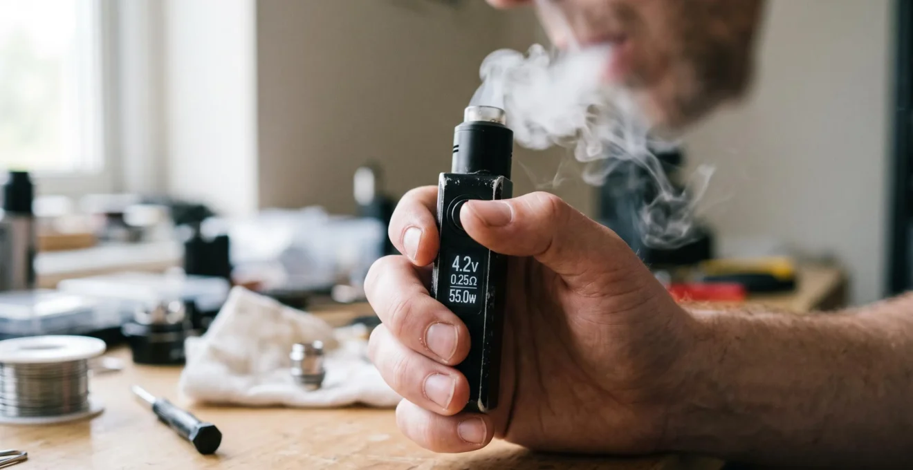
Real-time vape telemetry offers a window into how a regulated device responds to electrical conditions. Voltage, coil resistance, battery information and, on compatible devices, estimated temperature can help explain why delivered power changes during operation. These readings are particularly useful when a device behaves differently from its usual pattern, displays an atomizer warning or appears to lose power unexpectedly.
The important distinction is that telemetry reveals electrical behaviour, not necessarily its underlying cause. A changing voltage reading may reflect ordinary battery loading, while an abrupt resistance change could indicate a connection problem, thermal effects or the way the controller processes measurements.
Understanding these differences requires more than watching numbers fluctuate. The useful approach is to identify what each reading represents, compare it with a reliable baseline and observe whether deviations repeat. Manufacturer documentation for regulated controllers provides the technical foundation for interpreting these signals without treating every variation as a hardware defect.
Real-Time Vape Telemetry: Essential Points
- Regulated-device microchips monitor electrical conditions and adjust output according to operating limits and available protection functions.
- Voltage and resistance readings become more useful when compared across operating states and against a known baseline.
- Sudden, recurring resistance instability or intermittent atomizer warnings justify checking accessible connections and coil compatibility before further use.
- How Do Integrated Control Microchips Manage a Regulated Vape Device?
- Why Does a Vape Microchip Monitor Voltage, Resistance and Temperature Signals?
- Why Do Vape Telemetry Values Shift While the Device Is Being Used?
- How Can You Interpret Vape Screen Data Without Focusing on a Single Number?
- Simple Display or Detailed Telemetry: Which Vape Screen Information Is Actually Useful?
- Which Telemetry Changes Can Signal a Loose Coil or Poor Contact?
- Which Resistance Changes Suggest a Loose Coil Connection?
- When Should You Check Vape Telemetry After Installing a New Coil?
How Do Integrated Control Microchips Manage a Regulated Vape Device?
A regulated vape device uses an integrated control microchip to monitor electrical inputs, determine whether operating conditions remain within supported limits and manage power delivery to the heating coil. Its control circuitry can adjust output or activate protection functions. Telemetry displayed on the screen represents selected measurements, calculations and controller states from this regulation process.
Unlike a mechanical device, where the electrical path is primarily governed by the battery, switch and connected load, a regulated device incorporates electronic control between the power source and atomizer. Depending on the design, a switching converter can increase or decrease output voltage to support the selected power setting within the device’s operating limits.
The Evolv DNA 75 technical datasheet documents a regulated DC-DC power controller with wattage regulation, battery monitoring, resistance-related functions and temperature protection. Its specified maximum output is 75 watts, a specification belonging to that particular controller rather than to regulated devices generally.
Understanding what the controller measures is essential. Battery voltage and atomizer electrical characteristics can be monitored, while other screen values may be derived from those measurements. For example, electrical power can be calculated from voltage and current, and a compatible coil’s temperature can be estimated from changes in resistance.
Displayed coil temperature is not necessarily a direct temperature-sensor measurement. On controllers using resistance-based temperature control, it is an estimate that depends on the coil material, a reliable resistance reference and appropriate configuration. Localized hot spots may not be represented accurately by the displayed estimate.
The controller also makes decisions that affect what appears on the display. If a protection limit is reached, the device may reduce delivered power even though the selected wattage remains unchanged. In that situation, a difference between requested and actual output does not automatically mean that the coil or battery is defective.
Another important distinction concerns voltage labels. An output-voltage reading describes electrical delivery to the atomizer, whereas battery voltage concerns the power source. These values need not match because the regulation circuit operates between them.
Once this control loop is understood, voltage, resistance and temperature information can be interpreted as related signals serving both regulation and protective functions.
Why Does a Vape Microchip Monitor Voltage, Resistance and Temperature Signals?
A vape microchip monitors voltage, resistance and, where supported, temperature-related signals to maintain operation within defined electrical and thermal limits. Voltage monitoring supports battery protection, resistance readings help detect incompatible loads or connection faults, and temperature estimation can restrict coil heating. These functions provide the operating context behind the numbers shown on the device screen.
Each signal contributes different information, but their value comes from how the controller uses them together.
- Battery voltage: helps the controller identify conditions in which the battery can no longer support normal operation or has reached a defined low-voltage limit.
- Atomizer resistance: informs electrical load calculations and helps detect conditions such as a short circuit, unsupported resistance or an open connection.
- Temperature-related information: supports power limitation on compatible temperature-control systems, using suitable coil materials and the required resistance reference.
These inputs influence one another. For a resistive load, electrical power depends on the voltage applied and the resistance of the load. At a fixed applied voltage, a resistance change alters calculated power. A regulated controller may compensate by changing its output, provided the requested operating conditions remain achievable.
Heating can also change coil resistance. In temperature-control operation, the controller uses this relationship to estimate coil temperature and adjust power when the configured limit is approached. The resulting change in delivered wattage can therefore be an intentional control response.
The terminology matters: the controller may monitor board temperature directly through an electronic sensor while estimating heating-coil temperature from resistance. Those are different quantities and should not be interpreted interchangeably.
Electrical conditions are assessed during operation, and some controllers update their output as the draw progresses. However, internal measurement frequency and visible screen refresh frequency are not necessarily identical. The supplied manufacturer documentation does not establish a universal sampling interval for vaping devices.
A screen may consequently show only selected or processed values from a more active internal control process. A brief reading does not reveal every adjustment made during the draw.
Protective regulation also has practical limits. Temperature protection depends on correct configuration and compatible materials; it should not be treated as a guarantee against dry heating or other malfunction.
Recognizing these relationships makes it easier to understand normal fluctuations before interpreting them as potential faults.
Why Do Vape Telemetry Values Shift While the Device Is Being Used?
Vape telemetry values can shift during use because electrical loading changes battery voltage, coil heating can alter resistance, and the controller may adjust output to maintain the selected operating mode. These variations are not automatically faults. Their significance depends on which quantity is displayed, when it changes and whether the pattern repeats under comparable conditions.
One common effect is battery voltage sag. When the battery supplies current, its terminal voltage can decrease because of internal resistance and other electrochemical characteristics. After the load is removed, the voltage may recover.
Battery University‘s explanation of internal resistance and voltage drop describes why loaded voltage can differ from unloaded voltage. It also explains how increased internal resistance can restrict power delivery and contribute to early equipment shutdown.
This general battery principle applies to interpreting a battery-voltage reading, but it should not be confused with atomizer output voltage. A controller can regulate its output while the battery’s voltage changes under load.
Another source of variation is coil heating. The resistance of certain coil materials changes with temperature. Temperature-sensitive controllers intentionally use that relationship, while ordinary power-mode devices may display a resistance value whose behaviour depends on the manufacturer’s measurement and display implementation.
A third source is active compensation. When a controller approaches a thermal or electrical limit, it may adjust delivered power. A changing output-voltage or wattage reading may therefore demonstrate that the regulation system is responding as intended.
Interpreting those movements requires an appropriate comparison:
- Identify whether the displayed voltage refers to the battery or atomizer output.
- Record the device’s available idle readings when the coil is at a comparable temperature.
- Observe the available operating readings during normal use, without changing or touching electrical connections.
- Compare the same quantities over several operating cycles, noting whether changes are repeatable.
- Stop using the device if recurring errors, abnormal heating or unexplained electrical instability appears.
The aim is to distinguish a repeatable operating pattern from an irregular event, not to establish a universal numerical threshold.
A nearly constant screen value also requires caution. Some displays round measurements or update less frequently than the underlying control circuit operates. Apparent stability may therefore reflect display behaviour rather than perfectly constant electrical conditions.
Conversely, a changing reading does not prove that regulation is healthy. Telemetry must be considered alongside normal operation, warning messages and the controller’s documented capabilities.
The next step is to interpret several readings together, using a stable reference rather than relying on a single screen value.
How Can You Interpret Vape Screen Data Without Focusing on a Single Number?
Vape screen data is most useful when voltage, resistance, selected power and available temperature-related information are interpreted as a connected pattern. A single reading rarely identifies a hardware fault. Comparing several values with the device’s normal behaviour helps separate expected operating changes from unusual, persistent or recurring deviations.
Begin by establishing what is normal for the specific device, coil and operating mode. A resistance value measured with a freshly installed, cool coil provides a useful reference, while selected wattage records the intended power setting. Battery-voltage information can help describe the power source’s condition when the same measurement is available.
This reference is more meaningful than assuming that every device should display the same resistance, voltage drop or temperature response. Different coils, controllers and operating modes can produce different patterns without indicating a malfunction.
Consider an explicitly hypothetical situation: a device shows a consistent cold resistance after installation, but later displays a different value immediately after use. If the coil is warm, temperature-dependent resistance may explain part of the difference. That observation alone does not establish that the connection is loose.
Now consider a different hypothetical pattern: cold resistance changes abruptly between repeated checks, accompanied by intermittent atomizer warnings. This combination provides stronger grounds for investigating electrical contact integrity than the resistance variation alone.
Useful interpretation therefore considers three dimensions:
- Operating state: whether the reading was taken while idle, under load or after heating.
- Deviation from baseline: whether the result differs from previous comparable readings for the same setup.
- Associated symptoms: whether warnings, interruptions or unexpected device behaviour occur at the same time.
Display precision is another limitation. A screen may round resistance to a limited number of decimal places, average measurements or refresh values at intervals. A small visible difference is not necessarily evidence of a meaningful physical change.
Temperature-control devices introduce an additional complication: displayed resistance may be normalized to a reference temperature, or the controller may maintain a locked cold-resistance value. The number on the screen may therefore be a processed reference rather than a continuously updated raw measurement.
For reliable comparisons, record the displayed field’s label, operating mode and relevant device settings. Measurements from unlike states should not be treated as equivalent.
Once the relevant patterns are understood, the amount of information required depends on whether the goal is everyday operation or more detailed hardware troubleshooting.
Simple Display or Detailed Telemetry: Which Vape Screen Information Is Actually Useful?
A simple vape display is generally sufficient for checking selected power, battery status and basic device warnings. Detailed telemetry becomes more useful when investigating changes in coil resistance, battery voltage under load or controller power limitation. Additional measurements improve interpretation only when their meanings and normal reference conditions are understood.
Basic displays reduce the amount of information users must interpret during ordinary operation. A selected wattage value helps confirm the intended setting, while a battery indicator provides a simplified view of remaining charge or voltage-related status.
However, a battery icon does not necessarily reveal voltage sag during operation, and a selected wattage figure does not always represent the power actually being delivered at a particular moment.
More detailed interfaces can provide output voltage, atomizer resistance, battery or individual-cell voltage, estimated temperature and puff-related statistics. The DNA 250 manufacturer documentation, for example, identifies additional monitoring parameters such as output current, average power during the previous puff and puff duration.
Not every regulated device makes these parameters available. Their meaning and availability must be established from the relevant controller documentation.
The following comparison shows when each display type provides useful information.
| Diagnostic purpose | Simple display | Detailed telemetry |
|---|---|---|
| Confirm selected wattage | Usually sufficient when wattage is shown | Can provide additional delivered-output context |
| Check battery status | Provides a simplified indicator | May expose battery voltage and loaded behaviour |
| Identify atomizer warnings | Useful when warning messages are supported | May add resistance information for comparison |
| Investigate changing coil resistance | Limited unless resistance is displayed | Supports baseline and repeat-reading comparisons |
| Understand temperature-control response | May show only a configured setting | May distinguish estimated temperature and delivered power |
| Review previous operating conditions | Often limited | Some controllers provide puff duration or average-power information |
The most useful screen is not necessarily the one displaying the largest number of measurements. It is the one that provides relevant, correctly labelled information for the question being investigated.
For example, someone checking whether a device is ready for normal operation may need only basic status information. Someone investigating recurring connection errors benefits more from resistance readings and warning history, provided the available display supports them.
Detailed screens also create opportunities for misinterpretation. A temperature estimate can appear precise without capturing every local heating condition, while a battery-voltage figure may seem alarming if its loaded or unloaded state is unknown.
For diagnostic purposes, field definitions and comparable measurements are more valuable than visual complexity alone.
When the problem involves erratic resistance or intermittent atomizer detection, even a small set of well-understood readings can provide useful clues about the electrical connection.
Which Telemetry Changes Can Signal a Loose Coil or Poor Contact?
Possible signs of a loose coil or poor electrical contact include abrupt resistance changes, intermittent atomizer warnings and readings that change after a coil or tank is reseated. These symptoms suggest inconsistent electrical continuity, but they do not identify the defective component by themselves. Coil condition, connector contamination and device compatibility must also be considered.
A regulated controller depends on an electrical connection between its output terminals and the heating element. If that connection becomes intermittent, the resistance detected by the controller may change unexpectedly or become temporarily unavailable.
Depending on the device, the resulting behaviour may include a check-atomizer message, an open-circuit indication or interruption of power delivery. Such symptoms justify investigation, but they are not exclusive to a loose coil.
Innokin‘s atomizer troubleshooting FAQ identifies connection problems, contaminated contacts, defective coils and resistance compatibility as relevant considerations when diagnosing atomizer errors.
The distinction matters because several causes can produce similar screen behaviour:
- Improperly seated coil or tank: the electrical connection may not be reliable.
- Contaminated contacts: condensation, dust, lint or other debris may interfere with electrical continuity.
- Damaged connector: worn threads or electrical pins may prevent dependable contact.
- Defective coil: an internal fault can produce symptoms resembling a poor external connection.
- Unsupported resistance: the controller may reject a coil outside its specified operating range.
A practical troubleshooting order begins with switching the device off and allowing it to cool. Accessible components can then be checked against the manufacturer’s installation guidance.
Inspect the coil or tank seating without forcing the threads, examine accessible contact surfaces and check for visible contamination or damage. Cleaning should follow the device manufacturer’s instructions, with all surfaces completely dry before reassembly. Battery compartments and internal electronics must not be opened or modified as part of this procedure.
If the problem persists, a known-compatible replacement coil may help determine whether the original coil is involved. Recurring errors after appropriate checks may indicate a fault requiring manufacturer support or professional service.
An unstable connection may also disrupt normal power delivery, although the exact response depends on the controller. Protective shutdown or atomizer errors may occur, while other behaviours cannot be inferred without device-specific evidence.
In particular, an erratic resistance reading does not prove that irregular power pulses have damaged the wick or shortened coil life. The available technical sources do not establish that causal relationship as a general rule.
Never attempt to reproduce a suspected contact fault by loosening a connection while firing the device. Diagnostic comparisons should be performed with the connection correctly installed, and persistent instability is a reason to discontinue use.
Resistance readings can refine that assessment further, particularly when changes are compared across time and after a controlled, powered-off reseating check.
Which Resistance Changes Suggest a Loose Coil Connection?
A loose coil connection may be suspected when resistance changes abruptly between comparable cold-state readings, becomes intermittently unavailable or returns to its previous value after the coil is reseated. These patterns are more suggestive than a small isolated difference. Temperature, controller measurement behaviour and coil condition must still be considered before identifying contact instability.
Resistance is particularly useful because it describes an electrical property of the connected atomizer. However, the displayed figure may be affected by the controller’s measurement method, rounding, thermal conditions and resistance-reference settings.
The strongest comparison is therefore not simply between two numbers. It is between measurements made under comparable conditions.
For instance, a warm coil may produce a different reading from the same coil when cool. Such a difference can arise from the material’s resistance-temperature relationship and should not automatically be attributed to mechanical looseness.
In contrast, an abrupt change observed after the coil has cooled, particularly when accompanied by an atomizer error, provides a stronger reason to inspect electrical continuity.
It is also important to distinguish resistance drift from normal coil wear. Coil deposits, thermal exposure and physical deterioration may affect performance over time, but gradual resistance changes are not a universal or definitive marker of aging. Similarly, sudden changes are not exclusively caused by loose contacts.
The Evolv DNA 250 documentation discusses cold-resistance references and resistance-lock functionality. On supported devices, locking preserves a selected reference for temperature estimation. This can be useful in particular operating circumstances, but it does not repair defective electrical contact.
A difference between locked and unlocked resistance displays must therefore be interpreted in the context of the controller’s reference-management behaviour. It does not independently prove that a coil connection is loose.
A structured comparison can help make this distinction without deliberately provoking an electrical fault.
Five Checks for Repeatable Resistance Diagnosis
- Record the baseline. With the correctly installed coil cool and the device idle, note the displayed resistance, device mode and coil identification. Deliverable: a labelled initial reading.
- Document the symptom. Note any warning message or unexpected resistance change during ordinary operation, without manipulating connections while powered. Deliverable: a short symptom record.
- Inspect the connection safely. Switch off the device, allow it to cool and check accessible coil seating, connector condition and cleanliness according to manufacturer instructions. Deliverable: an inspection result.
- Repeat the cold-state reading. After correct reassembly, compare the resistance with the initial value under similar conditions. Deliverable: a before-and-after comparison.
- Determine the next action. If instability persists, discontinue use and follow manufacturer guidance on compatible coil replacement or service. Deliverable: a documented decision to retain, replace or service the affected component.
This method emphasizes repeatability and observed symptoms rather than imposing an unsupported resistance threshold. It also avoids treating software settings as substitutes for physical connection integrity.
A useful outcome may be confirmation that readings remain consistent after correct assembly. Alternatively, repeated inconsistency can justify taking the device out of service pending further assessment.
The same baseline principle is especially valuable when a new coil is installed, because its initial readings provide a reference for later comparisons.
Key Takeaways Before Installing a New Coil
- Record a reliable cold-state reference rather than relying on a generic resistance threshold.
- Keep temperature, operating mode and controller settings comparable when interpreting later readings.
- Resolve connection warnings before normal operation; a fresh coil should not be used to dismiss persistent device faults.
When Should You Check Vape Telemetry After Installing a New Coil?
Vape telemetry should first be checked after a new coil is correctly installed and before normal operation, using its cool-state resistance as a reference. Readings can then be reviewed after the manufacturer’s recommended preparation and initial operating period. Comparing these checkpoints helps identify unexpected deviations while accounting for heating and controller-specific resistance behaviour.
The first useful checkpoint is installation. With the device correctly assembled and the coil at a stable, cool temperature, its displayed resistance can be compared with the coil’s specified compatibility range and the device’s supported operating limits.
A reading outside those limits, or an atomizer warning, should be investigated before the device is used. The resistance range supported by one device must not be assumed to apply to another model.
The second checkpoint follows the manufacturer’s preparation instructions. For a replaceable wick-based coil, this may include the prescribed priming procedure and an appropriate initial operating setting. Those instructions vary by coil and device; telemetry alone does not establish that a wick is ready for use.
After initial operation, coil temperature may differ from its installation state. On materials with temperature-dependent resistance, the resulting displayed value may also change. That difference is not automatically evidence of a defect or a predictable universal bedding-in process.
The third checkpoint is a repeat reading after the coil has returned to a comparable cool state. This helps separate temporary thermal effects from more persistent differences in the connection or measurement reference.
Cold resistance is particularly relevant to temperature-control devices. The Evolv controller documentation explains that temperature estimation depends on an appropriate resistance reference, and that connecting an atomizer while it is still warm can produce inaccurate temperature calculations.
This means installation checks should also consider whether the controller has correctly recognized a new atomizer and whether resistance-lock or temperature-reference settings remain appropriate. The relevant settings depend on the controller and its documented operating procedure.
Recording the initial values creates a small but useful diagnostic history. A simple entry can include coil type, displayed cold resistance, operating mode, installation date and any warning observed. These details provide context if unusual behaviour develops later.
The purpose is not to monitor every minor fluctuation indefinitely. It is to preserve a trustworthy point of comparison so that future changes can be evaluated more efficiently.
For the next coil change, record the initial cold-state resistance, confirm compatibility and retain the reading for future comparison. If errors or unexplained instability appear, stop using the device and follow its manufacturer’s troubleshooting instructions rather than relying on telemetry alone.
Does a changing voltage reading mean the vape battery is failing?
No. Battery voltage commonly decreases under electrical load because of internal resistance and can recover after the load is removed. The meaning of a displayed voltage also depends on whether it represents battery voltage or regulated output voltage. Unexpected shutdowns or recurring warnings require further investigation, but voltage movement alone does not identify a defective battery.
Can vape telemetry detect an internal battery problem with certainty?
No. Battery telemetry may reveal unusual voltage behaviour or a protective shutdown, but similar symptoms can arise from electrical contacts, load conditions or controller limitations. A device screen is not a substitute for appropriate battery testing. Damaged, overheating or otherwise suspect batteries should not remain in use pending assessment.
Why might a temperature-control vape display a different resistance from a basic wattage device?
Some temperature-control systems use a normalized cold-resistance reference or a resistance-lock function to support temperature estimation. A displayed reference may therefore differ from a continuously measured warm-coil value. The correct interpretation depends on the controller, coil material and selected operating mode.
Can detailed vape telemetry replace physical inspection of electrical contacts?
No. Telemetry can indicate irregular electrical behaviour but cannot reliably distinguish every cause. Contamination, coil defects, mechanical damage and compatibility problems may produce overlapping symptoms. Physical inspection of accessible, powered-off components and manufacturer-guided troubleshooting remain important when a connection fault is suspected.
Is there a universal resistance-change threshold that indicates a loose coil?
No universal threshold is established by the technical sources used here. Resistance behaviour depends on coil material, temperature, measurement resolution, controller design and electrical connection quality. Repeated abrupt deviations under comparable conditions, especially alongside atomizer warnings, provide a more meaningful reason to investigate than an isolated numerical difference.