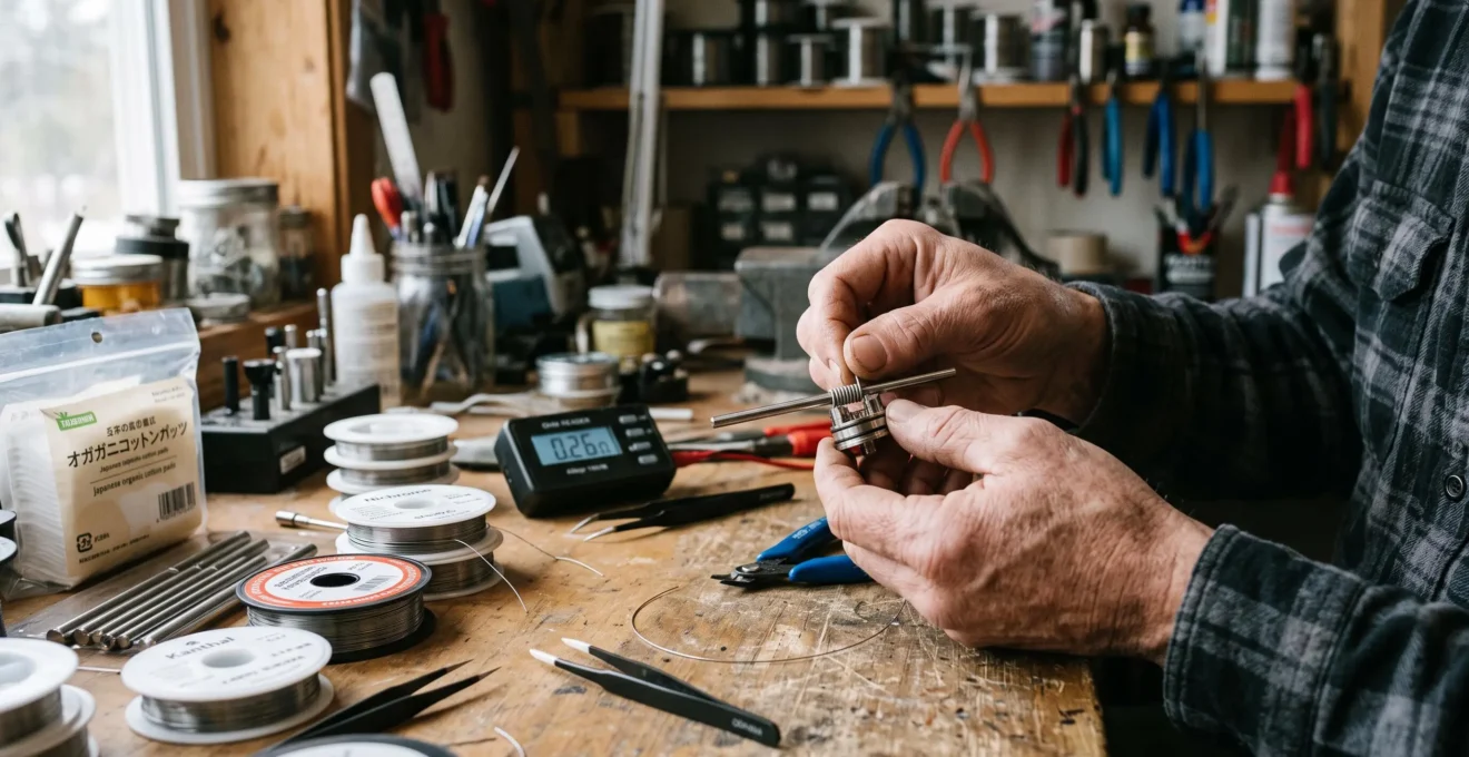
Choosing custom heating wire for a rebuildable vape coil starts with three connected decisions: material, wire dimensions and coil construction. Together, these determine electrical resistance, heating response and whether the finished coil fits the atomiser deck and the operating mode of a regulated device.
Wire gauge alone cannot predict how a build will perform. A thicker conductor generally provides lower resistance per unit length, but increasing its diameter also adds metal that must be heated. Changing the number of wraps, coil diameter or material further alters the result. A multi-strand construction introduces additional variables, including surface area, thermal mass and installation complexity.
The most dependable approach is to work backwards from the intended resistance, available deck space and device specifications. A calculator can establish a plausible configuration, but the installed coil must still be inspected and measured. The aim is not simply to reach a particular resistance reading: it is to select a compatible, mechanically stable construction that can be reproduced without unnecessary adjustments.
Custom heating wire: the essential decisions
- Match geometry to resistance: thicker wire lowers resistance per unit length, while longer wire increases it. Account for wraps, coil diameter and lead length together.
- Match material to device mode: verify the alloy against the regulated mod’s wattage or temperature-control specifications before installation.
- Verify the actual build: check deck clearance, secure connections and measured resistance rather than treating calculated values as guaranteed.
- Why Does Thicker Heating Wire Change Coil Resistance and Ramp-Up Time?
- How Can You Prepare Heating Wire for a Clean and Stable Coil Build?
- Single-Strand or Multi-Strand Heating Wire: Which Fits Your Build Goals?
- Which Heating Wire Materials Should Not Be Used in the Wrong Vape Mode?
- How Can Target Resistance Help Narrow Down Custom Heating Wire Choices?
- How Can You Wrap a Consistent Coil Without Distorting the Wire?
- How Can You Check Coil Resistance Before Using a Rebuildable Atomiser?
- Which Coil-Building Techniques Improve Consistency on a Rebuildable Atomiser?
Why Does Thicker Heating Wire Change Coil Resistance and Ramp-Up Time?
Thicker heating wire usually has lower electrical resistance than thinner wire of the same material and length because its larger cross-sectional area allows current to pass through more conductive material. However, thicker wire also contains more metal to heat. Its ramp-up therefore depends on thermal mass, applied power and the finished coil’s resistance, not gauge alone.
The underlying electrical relationship is expressed as R = ρL/A, where R is resistance, ρ is material resistivity, L is conductor length and A is cross-sectional area. The OpenStax explanation of electrical resistivity and resistance establishes why increasing conductor diameter reduces resistance when material, length and temperature remain unchanged.
For American Wire Gauge (AWG), a lower gauge number indicates a thicker wire. This matters when comparing spool labels: choosing a lower numerical gauge is not the same as choosing a thinner conductor.
Ramp-up introduces a separate thermal question. Three variables need to be considered together:
- Thermal mass: more metal generally requires more energy to produce a comparable temperature rise.
- Target resistance: the finished resistance interacts with the device’s power delivery and electrical operating limits.
- Applied wattage: higher delivered power can increase the heating rate, although the relationship depends on the build and its operating conditions.
At modest wattage, a thick, high-mass coil may respond slowly. At substantially greater power, it may heat much more rapidly and become difficult to manage if airflow and liquid supply are insufficient. Neither low resistance nor fast ramp-up establishes that a configuration is appropriate for a particular device.
For a restrictive-lung build, the useful starting point is often a compact coil that can respond at the intended operating power. A direct-lung configuration may offer more physical space and airflow for a larger coil, but these are design considerations rather than universal gauge prescriptions.
Increasing wire thickness can also create a geometry problem. If the lower resistance per unit length requires additional wraps to approach the target, the finished coil may become too wide for its deck. Increasing the inner diameter further increases wire length per wrap and occupies additional space.
The practical choice is the geometry that fits the deck and the intended regulated power range. Once that relationship is understood, attention can shift to the condition of the wire before it is wrapped.
How Can You Prepare Heating Wire for a Clean and Stable Coil Build?
Prepare heating wire by checking its material, examining its surface, cutting a manageable length and removing bends without damaging its structure. Clean, straight wire is easier to wrap consistently and secure in an atomiser. Avoid assuming that torching or dry-burning is suitable for every alloy: preparation methods should follow material and manufacturer guidance.
Wire taken directly from a spool may retain curvature from winding. It can also carry handling residues, dust or small surface defects. These conditions do not automatically make the conductor electrically unsuitable, but they can interfere with controlled wrapping, lead positioning and connection quality.
A practical preparation routine follows the wire’s construction:
- Identify the material. Confirm the spool’s alloy designation and intended device compatibility before changing its shape.
- Cut a workable length. Allow sufficient material for the intended wraps and leads without pulling the spool across the work surface during installation.
- Inspect the conductor. Look for pronounced kinks, damaged strands, contamination or irregularities that could compromise the finished coil.
- Straighten gently. Reduce the spool’s curvature using controlled tension and appropriate tools, without stretching or reducing the wire’s cross-section.
- Clean conservatively. Where the material supplier permits it, remove suitable surface residues with an appropriate non-abrasive method and ensure the wire is dry before use.
Round single-strand wire generally tolerates controlled straightening better than shaped or multi-strand products. Flat wire can twist, while braided or wrapped constructions can become uneven if pulled too aggressively. Any deformation may affect how the wire seats in terminals or wraps around a mandrel.
Preheating is sometimes described as a way to clean or condition resistance wire, but it should not be treated as an automatic preparation step. Experimental findings on heating-related metal changes warrant caution, particularly with uncontrolled dry heating.
The illustration depicts an informal torch-heating method, not an established universal cleaning recommendation. A 2020 experimental investigation of Kanthal and Nichrome coils reported metal-composition changes after dry heating. The PubMed record of the experimental study on e-cigarette coil temperatures and metal loss describes these observations, but does not validate a preparation method for every heating-wire alloy.
Above 1,000 °C
Maximum coil temperatures reported under dry conditions in the study’s tested configurations, compared with temperatures below 300 °C under the tested liquid-saturated conditions. These laboratory results are not universal operating temperatures for rebuildable atomisers.
Mulder HA et al., Inhalation Toxicology, 2020; PMID: 33140978.
Wire preparation also affects later troubleshooting. A bent lead may sit poorly in a terminal, while damage to a multi-strand structure may complicate secure installation. Resistance instability following assembly should trigger a connection and clearance inspection rather than another round of uncontrolled heating.
Once the conductor is clean, identifiable and mechanically sound, the next choice is whether a straightforward single strand or a more complex wire construction better serves the intended build.
Single-Strand or Multi-Strand Heating Wire: Which Fits Your Build Goals?
Single-strand heating wire is generally the simpler choice for predictable wrapping, inspection and maintenance. Multi-strand constructions can provide greater surface area and different heating characteristics, but usually require more attention to deck clearance, power requirements and wicking. Neither construction guarantees better flavour: performance depends on geometry, material and installation quality.
A single-strand coil uses one continuous conductor of a specified material and cross-section. Its electrical behaviour is relatively straightforward to estimate from wire length and diameter. A builder can also inspect individual wraps, leads and possible contact points without working around an outer wire structure.
Multi-strand wire covers several constructions, including twisted and complex wrapped arrangements. These differ electrically and mechanically; they should not be treated as interchangeable simply because they contain multiple strands.
The comparison below shows how construction affects practical priorities rather than assigning an absolute performance ranking.
| Build priority | Single-strand wire | Multi-strand wire |
|---|---|---|
| Resistance planning | Relatively simple to estimate from material and conductor dimensions. | Requires the correct model for its strand arrangement and electrical connections. |
| Installation | Usually easier to shape, inspect and secure. | May require greater attention to deformation, width and terminal fit. |
| Maintenance | Exposed surfaces are comparatively straightforward to inspect. | Crevices and outer wraps can complicate cleaning and inspection. |
| Surface characteristics | Surface area is primarily determined by its dimensions and length. | Complex structures may provide additional exposed or textured surface. |
| Wicking | Generally easier to assess around a simple coil geometry. | Can be sensitive to cotton contact, liquid supply and construction-specific geometry. |
| Heating response | Depends on conductor mass, resistance and applied power. | May have substantially different mass and heat distribution. |
More metal surface does not automatically produce more useful vapour or better flavour. A complex coil still needs sufficient liquid contact and compatible airflow. If the construction requires more energy than the selected power setting provides, heating may feel delayed. Increasing power without checking liquid supply can introduce a different set of problems.
Multi-strand constructions also create mechanical vulnerabilities. Distorted outer wraps, damaged strands or inconsistent electrical connections can contribute to irregular heating. These issues must be diagnosed through inspection and appropriate verification, not assumed to be normal characteristics of complex wire.
For users who prioritise ease of maintenance and repeatability, single-strand wire offers fewer variables to control. Multi-strand wire is more appropriate when its particular geometry has a clear purpose and the deck, terminals and wicking arrangement can accommodate it.
After choosing the construction, the material itself becomes the next compatibility decision. A mechanically suitable coil can still be inappropriate if its alloy does not match the device’s operating mode.
Which Heating Wire Materials Should Not Be Used in the Wrong Vape Mode?
Heating wire must be matched to the regulated device’s supported operating mode. Kanthal and Nichrome are commonly associated with wattage-based operation, while nickel Ni200 and titanium Grade 1 are primarily associated with compatible temperature-control systems. Stainless steel may support either mode on suitable devices. Material labels alone are insufficient: check the exact alloy and manufacturer instructions.
In wattage mode, the device regulates power delivery according to its electronics and selected setting. Temperature-control (TC) operation instead estimates temperature partly from changes in the coil’s electrical resistance.
The important material property is the temperature coefficient of resistance (TCR), which describes how resistance changes with temperature. For TC to behave as intended, the device must be able to detect and interpret that change using a suitable material profile and reliable electrical connections.
The principal compatibility distinctions are:
- Kanthal: generally used for wattage-based builds. Its comparatively small resistance change with temperature makes it unsuitable for ordinary resistance-based TC profiles unless specifically supported by the manufacturer.
- Nichrome: commonly used in power mode. Its exact alloy composition matters, and it should not be assumed compatible with an unsupported TC setting.
- Nickel Ni200: principally a TC material. Do not use it in plain wattage mode unless the specific device and wire manufacturers explicitly authorise that application.
- Titanium Grade 1: intended for appropriate TC applications. Avoid uncontrolled heating and unsupported power-mode use, particularly because excessive heating can alter its surface.
- Stainless steel: some grades are suitable for wattage operation and supported TC profiles, but the grade and device configuration must match.
The Steam Engine technical explanation of temperature-control precision identifies baseline coil resistance and TCR as major factors in the sensitivity of resistance-based temperature estimation. Its model does not establish universal material compatibility or guarantee a particular device’s accuracy.
Material mismatches do not always produce an immediate error. A device might accept a coil while applying an unsuitable temperature algorithm, or produce measurements that appear plausible but are not reliable for the selected wire. The presence of a temperature-control menu therefore proves less than the exact supported alloy profile.
Before using a new wire, confirm its alloy designation, the device’s recognised material or TCR setting, the atomiser’s compatibility and the manufacturer’s operating restrictions. Repeat that check when transferring a familiar atomiser to a different regulated mod.
Once material and mode are confirmed, target resistance can be used to narrow the remaining choices of gauge, diameter and wrap count.
How Can Target Resistance Help Narrow Down Custom Heating Wire Choices?
Target resistance helps narrow heating-wire options by turning coil design into a reverse calculation. Start with a resistance compatible with the regulated device and intended power range, then evaluate material, gauge, inner diameter, wrap count and lead length. The calculated result is an estimate; the installed build must be measured before it is used.
Wire selection involves two principal geometric adjustments once the material is fixed: conductor cross-section and total conductor length. A thicker wire reduces resistance per unit length. More wraps, a larger inner diameter or longer leads increase the conductor length and therefore its resistance, with other variables held constant.
These adjustments interact. Selecting a thicker wire to change heating behaviour may require additional conductor length to reach the intended resistance. More wraps can make the coil wider; a larger diameter can compromise deck clearance or alter the available space for wicking.
A calculation is therefore useful only if the resulting configuration can be installed securely and remain physically separated from unintended conductive surfaces.
The Steam Engine coil-wrapping calculator provides estimates using inputs including material, AWG or diameter, target resistance, coil configuration, inner diameter and lead length. It also estimates characteristics related to heat capacity and heat flux.
Use an ohm calculator as a design filter:
- Choose the documented wire material and a proposed target within the device’s permitted operating range.
- Enter the wire diameter or AWG and the proposed coil configuration.
- Specify an inner diameter compatible with the atomiser and a realistic allowance for leads.
- Review the estimated wrap count, total wire length and thermal characteristics.
- Reject configurations that do not fit the deck or cannot be secured and wicked reliably.
Hypothetical example: a deck-space constraint
Consider an experienced builder with a regulated device, a target resistance already checked against the manufacturer’s specifications and a compact atomiser deck.
The first candidate uses relatively thick round wire. The calculator indicates that the proposed geometry needs more wraps than the deck can accommodate. Rather than forcing the coil into position or treating resistance as the only requirement, the builder evaluates a different gauge or another supported configuration and recalculates before installation.
The example illustrates a decision method, not a tested performance result or a recommendation for any particular electrical resistance.
Calculated and measured resistance can differ because of alloy tolerances, geometric approximations, lead length, connection resistance and deformation during installation. A small discrepancy may be unsurprising, but it is not automatically acceptable: its significance depends on the device’s limits, measurement reliability and the stability of the reading.
For TC builds, an accurate baseline resistance is particularly important because the device uses resistance variation to estimate temperature. For all builds, repeated unexpected changes demand investigation rather than adjustment of the target merely to match the displayed number.
After a plausible configuration has been selected, consistent wrapping determines how closely the finished geometry matches the original design.
How Can You Wrap a Consistent Coil Without Distorting the Wire?
Wrap a consistent coil using a stable mandrel, controlled wire tension and a repeatable spacing pattern. Keep the conductor aligned without flattening or kinking it, and form leads that reach the terminals without excessive bending. The goal is uniform geometry that remains stable during installation, rather than forcing every wire construction into identical-looking wraps.
A coil jig or mandrel establishes the intended inner diameter. This makes successive wraps easier to compare and helps limit geometric variation between rebuilds. A consistent diameter also supports more reliable resistance estimates because the wire length around each turn remains more predictable.
Steady tension matters, but greater force does not necessarily improve the result. Excessive pulling can deform softer conductors or disturb the outer strands of complex wire. Tool pressure can flatten round wire, creating visibly different sections of the coil.
Contact and spaced wraps require different handling. Contact coils keep adjacent turns together, while spaced coils maintain deliberate gaps. The appropriate arrangement depends on the material, construction and manufacturer guidance. For some TC materials, spaced wraps are preferable to reducing the possibility of electrical contact between adjacent turns.
Watch for three visible symptoms during forming:
- Irregular gaps: often indicate inconsistent spacing or tension during wrapping.
- Flattened or asymmetric turns: suggest that tools or wrapping pressure have distorted the original wire geometry.
- Kinked leads: can prevent secure terminal engagement or place mechanical stress on the finished coil.
Different constructions need different levels of force. A round single strand can often be adjusted with controlled pressure, while a loosely wrapped multi-strand structure may be damaged by the same movement. If a strand has separated or the conductor is visibly compromised, replacing the damaged section is generally more dependable than repeatedly reshaping it.
After wrapping, inspect the coil on its mandrel before fitting it to the atomiser. Compare the turn spacing, overall width and lead orientation with the available deck geometry. Do not rely on tightening the terminal screws to correct poor alignment.
Repeatability improves when the same mandrel size, material designation and wrapping method are used across comparable builds. Recording those parameters provides a more useful reference than remembering only the final resistance.
Once installed, the coil must pass electrical verification. A visually tidy shape is not proof that the resistance is stable or that every connection is secure.
How Can You Check Coil Resistance Before Using a Rebuildable Atomiser?
Check the installed coil with a suitable ohm reader or compatible regulated device before energising it. Compare the measured resistance with the calculated target and the device’s permitted range, then inspect for loose terminals, unwanted contact and unstable readings. Recheck after mechanical adjustments. A drifting or unexpected reading is a reason to stop and investigate.
The resistance check serves two purposes. First, it confirms whether the finished coil falls within the regulated device’s documented electrical operating limits. Second, it helps reveal faults introduced between planning, wrapping and installation.
A calculator models the intended conductor. The installed reading reflects the actual assembly, including its leads, terminal connections and any electrical faults. For this reason, measuring the finished build cannot be replaced by knowing the nominal resistance of the wire spool.
Use a reader designed for the application and verify that its contacts and power supply are in suitable condition. With the device unpowered during fitting and adjustments, inspect the terminal connections, insulators and clearance between the coil, deck and chamber. Where supported, check resistance after securing the coil and again following any manufacturer-approved adjustment or conditioning procedure.
Resistance readings require interpretation. A stable reading near the calculated estimate is more useful than a number that fluctuates between measurements. Loose leads, intermittent contact, damaged insulation or contact with the deck or chamber may cause unexpected changes.
The illustration shows resistance verification equipment. Reading a display does not itself establish that the device is suitable for firing or that the assembled atomiser is free of faults. Those conclusions require stable measurements, mechanical inspection and confirmation against the relevant specifications.
Five checks to document before first use
- Confirm material and mode: record the wire alloy and the compatible regulated-device setting verified against manufacturer documentation.
- Inspect installation: confirm that the leads are secured, insulation is intact and unintended metal-to-metal contact is absent; record any correction required.
- Measure resistance: record the installed reading from the compatible mod or ohm reader and compare it with the calculated target and device specifications.
- Repeat the measurement: confirm that the reading remains stable after securing the connections and making any necessary mechanical adjustments.
- Record the final configuration: note the measured resistance, coil material, geometry and device compatibility decision in a reproducible build record.
A single number should never override evidence of an intermittent connection. If the reading moves unexpectedly as the assembly is handled, discontinue testing under power and investigate the mechanical cause before proceeding.
Ongoing checks matter too. Resistance can vary with temperature and change as an assembly ages. Small differences between readings may reflect measuring conditions, but an abrupt or persistent unexplained change warrants inspection. A newly unstable build should not be treated as acceptable because it previously operated without an obvious problem.
Electrical verification establishes an essential baseline. The remaining work concerns positioning, liquid supply and thermal behaviour within the atomiser’s permitted operating conditions.
Key takeaways before final installation
- A correct resistance measurement does not compensate for poor coil placement or restricted clearance around the airflow system.
- Wicking must suit the actual coil construction and available liquid pathways, not just the nominal resistance.
- A reliable build is one whose material, geometry, measured resistance and installation conditions can all be documented and reproduced.
Which Coil-Building Techniques Improve Consistency on a Rebuildable Atomiser?
Consistent coil building depends on controlled installation as much as wire selection. Position the coil to suit the atomiser’s airflow, fit the wick without obstructing liquid movement and verify that the finished assembly remains electrically stable. Any manufacturer-approved thermal inspection should be conservative; repeated or excessive dry heating is not a substitute for correcting mechanical faults.
Start with coil placement. The heating element should sit in the position recommended for the atomiser, with appropriate clearance from the chamber, posts and other conductive surfaces. Its location relative to airflow affects how air passes around the coil and removes heat during normal operation.
A coil positioned poorly can produce uneven heating or unsatisfactory performance despite matching the intended resistance. Larger constructions may also restrict the airflow space that the deck was designed to provide. Check the assembled clearances rather than judging only the open deck.
Wicking introduces another mechanical variable. Cotton must contact the heating surface without being compressed so tightly that it restricts liquid movement. Excessive material in the coil or liquid channels can impair supply, while insufficient contact can leave parts of the conductor inadequately wetted.
The correct arrangement depends on the atomiser and wire construction. A simple single-strand coil and a complex multi-strand coil do not necessarily need identical wick density or positioning.
Heat treatment requires particular restraint. Conventional coil-building practices sometimes use short electrical pulses to identify uneven heating and adjust contact coils. However, the suitability of this procedure depends on the alloy and device instructions. Dry heating can produce temperatures and material changes that differ substantially from liquid-saturated operation, so prolonged glowing, uncontrolled torching and aggressive repeated pulsing should not be presented as universally safe maintenance methods.
If a manufacturer permits a relevant conditioning procedure, follow its specific restrictions. Otherwise, favour mechanical inspection, verified connections and replacement of a defective coil over improvised heating experiments. Never attempt adjustments while the coil is energised.
Common symptoms can help isolate the next inspection point:
| Observed symptom | Possible issue | Appropriate response |
|---|---|---|
| Sudden resistance change | Loose terminal, intermittent contact or damaged lead. | Stop use, disconnect power and inspect connections and insulation. |
| Uneven heating during a permitted diagnostic check | Irregular geometry, inappropriate contact or damaged conductor. | Discontinue heating; inspect the unpowered assembly and replace damaged wire. |
| Dry or harsh operation | Inadequate liquid supply, unsuitable power or poor airflow alignment. | Stop use and reassess wicking, placement and manufacturer-approved settings. |
| Liquid leakage or excessive saturation | Wick placement or liquid-flow imbalance. | Inspect the atomiser’s designated channels and adjust the wick according to its design. |
| Inconsistent results between rebuilds | Differences in geometry, connections, wick quantity or installation position. | Compare the build records and change one documented variable at a time. |
The table identifies possible causes rather than proving a diagnosis from symptoms alone. More than one factor can contribute to a problem, and an unexplained electrical fault should always take priority over performance adjustments.
Repeatability improves when the build record includes the alloy, gauge, construction, inner diameter, wrap count, approximate lead arrangement and measured resistance. Coil placement and wick arrangement are equally useful notes because these variables are not captured by resistance calculations.
The overall sequence matters: suitable material, workable geometry, careful preparation, controlled wrapping, secure installation, electrical verification and appropriate wicking. Each step reduces uncertainty in the next, making troubleshooting more systematic and avoiding unnecessary changes to several variables at once.
For the next rebuild, use the recorded configuration as a baseline. Keep the variables that produced a stable, compatible installation, identify any changes deliberately and verify the completed assembly again before use. This approach makes custom heating-wire selection a controlled technical process rather than repeated trial and error.
Does AWG refer to wire thickness or electrical resistance?
American Wire Gauge refers to conductor diameter, not directly to resistance. A lower AWG number means a thicker wire. Actual electrical resistance also depends on material resistivity, conductor length and temperature. Two wires with the same gauge but different alloys can therefore have different resistance values.
Can two coils with the same resistance require different wattage?
Yes. Equal electrical resistance does not imply equal thermal mass, surface area or airflow conditions. A simple round-wire coil and a larger multi-strand construction can have different heating responses despite similar measured resistance. The appropriate power setting must remain within device specifications and account for the actual coil, wicking and atomiser design.
Why can measured resistance differ from a coil calculator’s estimate?
A calculator uses selected alloy properties and estimated geometry. The installed coil may differ because of wire tolerances, lead length, deformation, temperature or terminal connections. Such differences make physical measurement essential. Unexpected or unstable readings require investigation rather than being dismissed as normal calculation error.
Can stainless steel heating wire work in both wattage and temperature-control modes?
Some stainless steel grades can be used in either mode when the regulated device supports the relevant alloy and operating profile. Stainless steel is not a single uniform electrical material. Confirm the exact grade and the mod manufacturer’s compatibility instructions rather than assuming that any stainless steel spool works with every TC setting.
Should a coil always be dry-burned before wicking?
No. Dry-burning is not a universal preparation requirement or a validated cleaning procedure for every alloy. Experimental research on selected Kanthal and Nichrome coils has documented temperature-dependent changes during dry heating. Follow the specific wire and device manufacturers’ instructions, avoid excessive heating and replace damaged or contaminated wire when its suitability cannot be established.