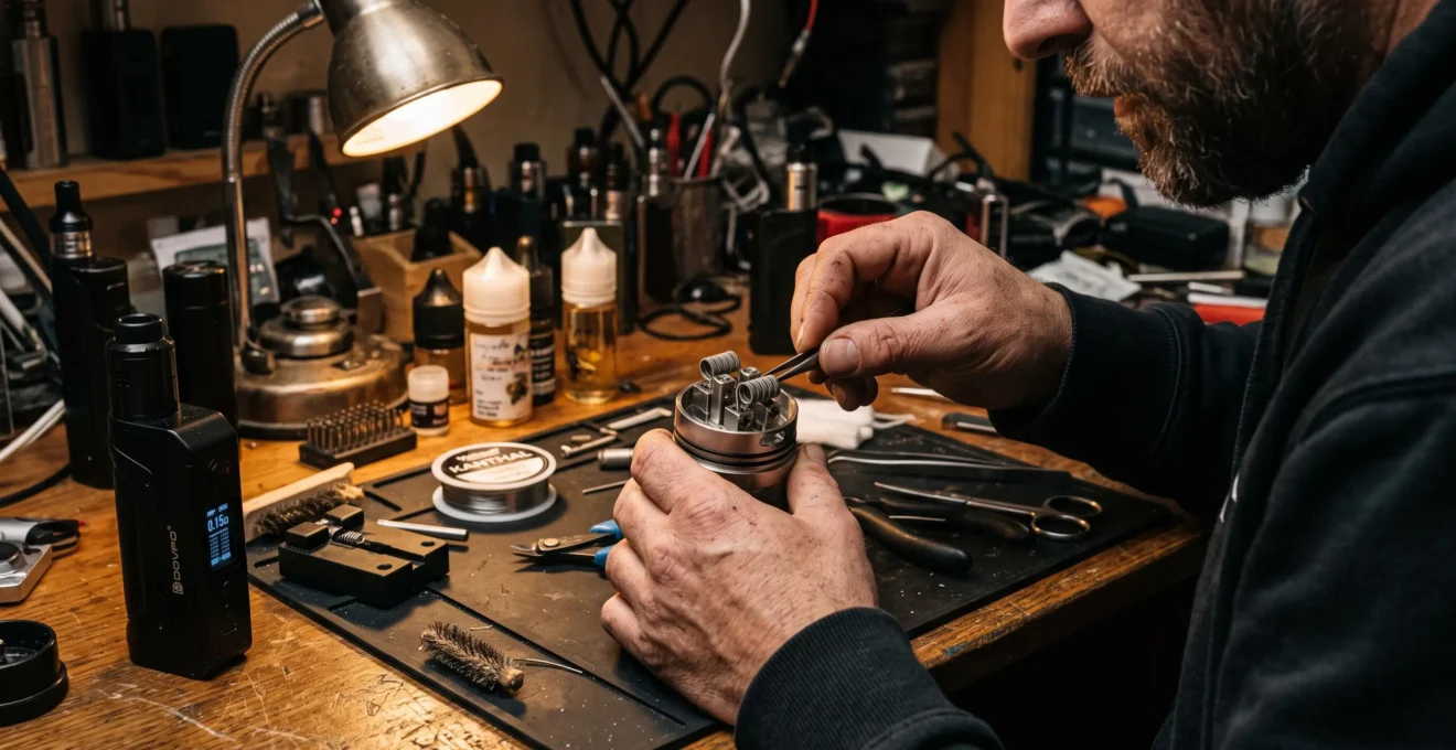
The best coil configuration for a rebuildable atomiser depends on more than resistance. Coil count, wire geometry, chamber dimensions and airflow position determine how electrical power becomes heat, how efficiently that heat reaches the e-liquid and whether the wick can replenish liquid fast enough.
A single-coil build generally offers a simpler electrical and mechanical arrangement. A dual-coil build increases the available heating surface but introduces additional demands on power delivery, airflow balance and wicking. Neither arrangement is automatically superior for flavour, vapour production or thermal stability.
Start with the atomiser’s supported configuration and available deck space, then consider its airflow system and the regulated device’s operating range. Wire material, coil diameter and lead positioning refine the result. Understanding these relationships is more useful than choosing a build solely because its displayed resistance appears suitable.
The following comparisons focus on rebuildable hardware, including the practical limitations that can turn an electrically functional installation into an unevenly heated one.
Coil configuration essentials
- Electrical behaviour: Two identical coils in parallel have half the resistance of either coil individually. Actual current and power depend on the device’s output conditions.
- Physical compatibility: Deck dimensions, chamber clearance and airflow coverage determine whether a single or dual configuration makes mechanical sense.
- Thermal control: Wire geometry, heating surface and reliable liquid supply matter as much as the resistance displayed on the mod.
- Why Does a Dual-Coil Build Behave Differently From a Single-Coil Build?
- How Can You Align Dual Coils for Balanced Heating and Airflow?
- Single or Dual Coil: Which Configuration Suits a Compact Atomiser Better?
- Which Dual-Coil Installation Errors Cause One Coil to Heat Faster Than the Other?
- How Can Airflow Position Determine the Most Effective Coil Configuration?
- How Can You Tighten Coil Leads in Build Posts Without Distorting the Coil?
- Compact or Wide Coil: Which Spreads Heat More Evenly in Your Atomiser?
- How Should You Choose Custom Heating Wire for a Rebuildable Vape Coil?
Why Does a Dual-Coil Build Behave Differently From a Single-Coil Build?
A dual-coil build behaves differently because its electrical connections alter total resistance and power distribution, while its additional heating surface changes thermal loading. In the parallel arrangements commonly considered for rebuildable decks, two identical coils halve the resistance of one coil. Whether that produces more heat depends on the voltage or total wattage supplied by the device.
For two identical resistive coils, each with resistance R, a parallel connection gives an equivalent resistance of R/2. Each branch receives the same applied voltage, while the currents through both branches add to produce the total current.
In an ideal fixed-voltage circuit, adding a second identical parallel coil doubles the total current and electrical power. Importantly, the original coil does not receive less power: each individual coil still experiences the same voltage and dissipates the same power as the original single coil.
A regulated device operating at a fixed total wattage behaves differently. If two identical parallel coils share the selected output power equally, each receives half of that total. The regulator adjusts its output voltage according to the load, within its operating limits.
Series wiring reverses the resistance relationship. Two identical coils connected in series have a combined resistance of 2R, and the same current flows through both. At equal total wattage, identical series and parallel pairs each divide power equally between their two heating elements, even though their required voltage and current differ.
These principles are established in the OpenStax explanation of series and parallel resistance. That textbook describes electrical circuits generally rather than certifying any particular atomiser wiring arrangement.
| Characteristic | Single coil | Two coils in parallel | Two coils in series |
|---|---|---|---|
| Equivalent resistance | R | R/2 | 2R |
| Electrical connection | One heating path | Separate current branches | One shared current path |
| Voltage across each coil | Full applied voltage | Full applied voltage | Half the applied voltage when identical |
| At fixed total wattage | All power in one coil | Half per identical coil | Half per identical coil |
| Physical heating area | One coil surface | Two coil surfaces | Two coil surfaces |
Two coils can distribute a given total power across more wetted heating surface. This can reduce average heat flux when the additional surface is effectively supplied with liquid. It does not guarantee denser vapour or better flavour: chamber geometry, heating efficiency, airflow and e-liquid delivery determine the actual result.
Neither vapour production nor battery runtime scales linearly with coil count. A higher selected wattage typically increases energy consumption, while heating mass, cooling and liquid availability can limit useful vaporisation.
Once the electrical arrangement is understood, physical alignment becomes the next consideration: identical coils cannot deliver consistent results if their positions and connections differ.
How Can You Align Dual Coils for Balanced Heating and Airflow?
Align dual coils by matching their dimensions, positioning them symmetrically around the deck’s centre and ensuring each receives comparable airflow. Both coils should have adequate clearance from metal surfaces and secure electrical connections. Verify the installation with the device disconnected before considering any controlled heating test permitted by the equipment manufacturer.
A matched dual-coil pair begins with the same wire type, gauge, inner diameter and wrap count. Even nominally identical coils can differ after installation if one is compressed, its leads are bent sharply or its clamping position changes.
For a conventional symmetrical dual-coil deck, examine the arrangement from above and from the airflow side. Both coil axes should be level and oriented consistently with their respective inlets. The inner wraps should not be pushed into the posts, and neither coil should sit closer to the chamber wall than the available clearance permits.
The ideal coil height is specific to the atomiser. Some decks are designed for airflow to strike the lower outside surface of each coil; others direct air toward the side or through a central opening. A coil does not necessarily need its bore directly in line with the airflow slot to work as designed.
Lead length matters electrically because resistance increases with conductor length. In most builds the active wraps account for much of the intended heating resistance, but substantially different exposed lead lengths or contact conditions can contribute to unequal behaviour.
Some experienced builders use brief, low-power dry pulses to identify visibly uneven heating in compatible resistance-wire builds. Such observations can reveal gross differences, but glow colour is not a calibrated temperature measurement. Heating bare metal also introduces burn, short-circuit and material-exposure risks.
Never pinch or adjust a coil while power is being applied. Any repositioning should occur only after firing has stopped and the coil has cooled sufficiently. Do not dry-fire nickel or titanium temperature-control wire, and follow the wire and device manufacturer’s instructions for other materials.
Heating symmetry is only part of the installation. Each coil also requires even contact with its wick. If one wick is compressed excessively or its tails obstruct liquid movement, electrical balance alone cannot prevent local overheating.
Five checks before using an aligned dual-coil build
- Compare coil specifications and confirm matching material, gauge, diameter and wrap count; record a matched pair.
- Inspect the unpowered deck from above and from the airflow side; confirm comparable placement and unobstructed inlets.
- Check every lead and wrap for unwanted contact with the deck, posts or chamber; confirm visible clearance.
- Verify secure clamps and a stable resistance reading on suitable equipment; record the measured resistance.
- Inspect wick contact and liquid access on both sides; confirm neither coil has visibly unsupported or excessively compressed wick sections.
A carefully aligned pair still needs enough physical space to operate. Compact atomisers may make that requirement more important than the theoretical benefits of using two coils.
Single or Dual Coil: Which Configuration Suits a Compact Atomiser Better?
A single-coil configuration is generally the more practical choice for a compact atomiser designed to accommodate one heating element. It preserves more clearance for airflow, wick placement and heat dissipation. A dual-coil setup becomes reasonable when the deck, chamber and airflow system are specifically designed to support two coils without crowding.
Chamber volume imposes a geometric constraint. Two coils occupy more physical space than one comparable coil, potentially reducing the area through which incoming air can circulate.
The limitation is not simply whether the coils fit between the posts. The installed assembly must also leave adequate space for the chamber or chimney, maintain separation from conductive metal and permit the wick to reach its intended liquid supply.
The choice can be organised around the intended operating characteristics rather than a universal flavour or vapour ranking.
| Decision factor | Single coil | Dual coil |
|---|---|---|
| Deck clearance | Usually easier to accommodate | Requires additional space and appropriate posts |
| Airflow arrangement | One heating position to serve | Both heating elements need effective coverage |
| Wicking maintenance | One wick assembly | Two wick assemblies to balance |
| Vapour potential | Depends on available heating surface and power | Additional surface may support greater output |
| Battery consumption | Depends on selected output power | May increase when operated at higher total power |
| Flavour concentration | Can benefit from a compact, suitable chamber | Depends on airflow, liquid supply and operating conditions |
Wicking is particularly sensitive to constrained space. In many compact tank designs, multiple wick tails must share a limited liquid-supply system. If one wick is too dense while the other permits comparatively easy liquid movement, the two coils can behave differently despite receiving similar electrical power.
There is also a thermal consequence. Two coils operated at greater combined power can place more heat into a small atomiser body. Limited metal mass and restricted cooling may allow the chamber and mouthpiece to warm during repeated use.
A single coil can therefore offer useful practical advantages without being inherently more efficient at every power setting. Similarly, a purpose-built compact dual-coil deck can perform adequately when its airflow and liquid supply were engineered for that arrangement.
If a dual-coil arrangement is mechanically supported but one coil behaves differently, examine the installation rather than immediately compensating with more power.
Which Dual-Coil Installation Errors Cause One Coil to Heat Faster Than the Other?
Unequal heating in a dual-coil build commonly points to differences in coil resistance, contact quality or mechanical installation. Loose post connections, mismatched wraps, inconsistent lead lengths and unintended metal contact can change the current flowing through each branch. A stable resistance reading and a complete unpowered inspection are essential before the build is operated.
Parallel coils receive the same voltage across their branches, assuming ideal connections. If their resistances differ, the lower-resistance branch draws more current and dissipates more electrical power at that voltage. This provides a useful starting point for understanding why nominally similar heating elements can behave differently.
A loose terminal introduces another complication. Additional contact resistance can reduce power delivered to the affected coil while dissipating energy at the connection itself. Consequently, the coil may heat weakly even as the terminal develops an unwanted local hot spot.
Unequal lead length can also change branch resistance, but it should not automatically be blamed for every heating imbalance. Differences in wire gauge, wrap count, damaged wire or terminal contact may have more significant effects.
Contact with the chamber wall, deck or chimney can create an unintended conductive path. Depending on the construction, this may partially bypass a heating element or produce a direct short. A device that still activates is not necessarily free from an electrical fault.
Cotton fibres alone should not be assumed to create a conductive short comparable to a metal-to-metal contact. Their more relevant effect is on liquid distribution and local cooling. The electrical connections and the wetting system should therefore be assessed separately.
Visual symptoms can narrow the investigation but rarely identify a fault conclusively. One coil glowing while the other remains dark may indicate an open or poorly connected branch, a substantial resistance mismatch or unequal cooling. Different glow speeds can also reflect variations in heating mass or geometry.
For fault isolation, disconnect the atomiser from its power source before touching the posts or moving any leads. Inspect the terminals, confirm the intended wire routing and measure resistance using equipment appropriate for the build. Qualified users may assess individual coils separately where the deck design permits, but disconnection and reconfiguration must never occur under power.
Do not fire a partially disconnected assembly with a loose lead near conductive surfaces. If a fault remains uncertain, replace the questionable coil or rebuild the assembly rather than repeatedly heating it.
A dry or under-supplied wick adds a separate source of unequal thermal behaviour. Experimental temperature measurements have shown that liquid availability significantly affects coil temperatures, although those results cannot establish a specific fault-diagnosis procedure for every rebuildable atomiser.
Once the electrical installation is verified, the next variable is the path taken by air around each heating surface.
How Can Airflow Position Determine the Most Effective Coil Configuration?
Airflow position influences coil configuration by determining which parts of the heating surface receive convective cooling and where vapour travels through the chamber. Bottom, side and combined airflow systems place different demands on coil height, orientation and spacing. The most effective layout is the one supported by the atomiser’s intended airflow geometry.
Air travelling around a hot coil carries away heat while transporting aerosol through the chamber. The actual cooling pattern depends on flow direction, inlet size, velocity, coil shape and nearby obstructions.
Air may pass around the outside of the wraps, strike the coil from below or enter the space through its centre when the design permits. Even when air flows through a coil bore, it does not guarantee equal cooling along every inner wrap.
A bottom-airflow deck often places its inlet beneath the heating element. Coil height changes the distance over which the incoming air spreads before reaching the wire. Raising a coil can alter coverage and chamber clearance simultaneously.
Side airflow creates a different relationship. A coil positioned near a lateral inlet may experience more direct cooling on its exposed side, while the opposite surface depends on how the flow travels around it.
In a dual-coil chamber, adding the second heating element reduces available free space unless the chamber is proportionally larger. This can redirect or restrict air movement. A narrower passage may increase local airflow velocity under some conditions, but it can also create uneven coverage or excessive restriction.
Airflow restrictions should therefore be treated as a trade-off, not as an automatic route to stronger flavour. Too little cooling relative to applied heat may raise operating temperatures even when vapour output does not increase correspondingly.
Experimental research on heating-wire film boiling and carbonyl formation demonstrates why thermal conditions matter. In the tested systems, emissions rose substantially after a critical heat-flux threshold was exceeded, while increasing energy input no longer produced proportional liquid vaporisation.
That study does not establish a universal airflow setting or an ideal single-versus-dual configuration. It does show why increasing heat without considering cooling and liquid supply can produce undesirable outcomes.
A practical comparison starts with the airflow geometry recommended for the atomiser, a properly wetted build and a conservative manufacturer-supported operating setting. Comparing fully open and moderately restricted airflow can reveal differences in resistance to the draw, perceived warmth and overall consistency.
However, airflow adjustments alone cannot reliably reveal which individual coil is drying first. That requires separate inspection of wick contact and liquid delivery. Stop using the assembly if it shows signs of overheating or a dry puff.
The airflow path establishes where the coil should sit; secure post connections then help preserve that placement during installation.
How Can You Tighten Coil Leads in Build Posts Without Distorting the Coil?
Coil leads should be secured while the coil body is mechanically supported, rather than by pulling wire through an already positioned heating element. Stabilising the coil prevents torque from changing its diameter, wrap spacing or alignment. The objective is a firm electrical connection without crushing the wire or damaging the post mechanism.
A coil behaves like a formed wire spring during installation. Force applied to a lead can transfer directly into the first wrap, especially when the wire is relatively soft or the coil extends some distance from its support.
If the screw clamps the lead before the wire is fully seated, tightening may drag it sideways. The result can be a tilted coil, altered wrap spacing or a displaced heating surface.
A coil rod or appropriately sized non-conductive positioning tool can help support the bore while the terminal is secured. With the atomiser completely disconnected from power, one hand stabilises the coil and the other tightens the post screw using the correct tool for that terminal.
Ceramic-tipped tools can be useful for careful positioning, but their insulating properties do not justify touching an energised coil or working on hot metal.
Firm clamping is different from overtightening. Excessive force may deform soft wire, damage screw threads or reduce the reliability of the mechanical connection. Lead flattening does not necessarily increase resistance by itself; the concern is damaged wire or unstable contact.
After tightening, inspect whether the coil still sits in its intended position, whether its wraps have shifted and whether any trimmed lead extends toward the atomiser chamber.
Measure resistance and confirm it is stable before installation is considered complete. If the manufacturer permits conditioning pulses for the selected wire, follow the relevant precautions and avoid using visible redness as a quantitative temperature measurement.
These mechanical checks are particularly useful after replacing a coil in a tightly spaced deck, where even a small change in diameter or tilt can affect clearance.
Once the coil is securely mounted, its width and number of wraps determine how much of the available chamber and wick surface it occupies.
Compact or Wide Coil: Which Spreads Heat More Evenly in Your Atomiser?
Neither a compact nor a wide coil automatically spreads heat more evenly. Heating uniformity depends on wire dimensions, resistance distribution, power, liquid contact and airflow. A larger inner diameter may accommodate more wick and expose a different heating geometry, while a narrower coil can fit more readily into a restricted chamber.
Coil inner diameter changes the length of wire required for a given number of wraps. Increasing the diameter while keeping wrap count and wire type constant generally increases conductor length and resistance, as well as heating surface and metal mass.
Consequently, a wider coil with fewer wraps does not necessarily have the same resistance or heating area as a narrower coil. The outcome depends on the particular combination of diameter, wrap count, gauge and material.
At a specified total power, increasing the effectively wetted heating surface can reduce average power per unit of surface area. This quantity is known as heat flux. Lower average heat flux may moderate local heating, but it cannot guarantee uniform temperature when liquid contact or airflow is uneven.
A narrow coil may concentrate its active surface within a smaller chamber region, which can be helpful for positioning. Yet tightly grouped wraps may interact thermally, and close contact between adjacent turns can produce a different heat distribution from spaced wraps.
A wider coil creates its own constraints. It needs sufficient clearance from the chamber and enough wick material to contact the active heating surface. If the wick leaves portions of the wire inadequately wetted, local temperatures can increase even though the overall coil has a comparatively large surface area.
145–334°C vs 322–1008°C
Reported peak coil-temperature ranges under wet-through-wick and dry-coil conditions, respectively, in experiments with a particular top-coil clearomizer. These are study-specific measurements, not general operating ranges or recommended temperatures for rebuildable atomisers.
Experimental study measuring electronic cigarette coil temperatures.
The clearomizer study illustrates how strongly liquid supply can influence temperature, but it does not establish which inner diameter is best for a modern rebuildable deck.
To compare geometries meaningfully, use the same specified wire material and equipment, and account for changes in conductor length, resistance and heating mass. Matching resistance alone does not ensure that two coils have equivalent thermal behaviour.
A useful assessment considers ramp-up response, fit within the chamber, airflow access and consistency of wick saturation. Persistent hot spots or dry-hit symptoms indicate that the arrangement needs reassessment rather than additional power.
Geometry determines how the available wire behaves physically. The final choice must also account for the electrical and thermal characteristics of the wire material itself.
Key takeaways before selecting heating wire
- Choose a coil layout that the atomiser can physically accommodate without compromising clearance, airflow or liquid delivery.
- Evaluate total power, effective heating surface and wick saturation together rather than treating resistance as a complete thermal specification.
- Confirm that the intended wire material is compatible with the device’s control mode before considering gauge or coil dimensions.
How Should You Choose Custom Heating Wire for a Rebuildable Vape Coil?
Choose heating wire by checking material compatibility, device control mode, resistance characteristics and the physical dimensions supported by the atomiser. Kanthal and suitable stainless-steel grades are commonly used in wattage-controlled builds, while nickel and titanium require compatible temperature-control operation. Wire gauge and coil geometry must then match the device’s electrical limits and the deck’s available space.
Different heating alloys change resistance with temperature at different rates. This matters because compatible temperature-control devices estimate heating-element temperature using measured resistance changes and an appropriate material profile.
Kanthal is generally selected for straightforward wattage-mode operation. It has relatively stable resistance over the relevant temperature range and is not ordinarily used for conventional resistance-based temperature control.
Stainless steel, in an appropriate documented grade, may be compatible with both wattage and temperature-control modes. However, its suitability for temperature control depends on the device supporting the corresponding resistance-temperature characteristics.
Nickel and titanium heating wires introduce more restrictive handling requirements. Pure nickel and titanium intended for vaping should only be used with compatible temperature-control equipment following the wire and device manufacturers’ instructions. Dry-firing and uncontrolled overheating must be avoided.
| Wire material | Typical operating approach | Important consideration |
|---|---|---|
| Kanthal | Wattage mode | Check gauge, build resistance and power compatibility |
| Suitable stainless-steel grade | Wattage or supported temperature-control mode | Confirm the exact alloy grade and device profile |
| Nickel | Compatible temperature-control mode only | Avoid dry-firing and unsupported operating modes |
| Titanium | Compatible temperature-control mode only | Avoid overheating and follow strict material-specific precautions |
Gauge changes how much resistance a given length of wire provides. For the same alloy, thinner wire generally has greater resistance per unit length and less thermal mass. Thicker wire generally has lower resistance per unit length and more metal to heat.
This influences ramp-up behaviour, but there is no universal rule that a thicker coil always heats more slowly. Actual response also depends on applied power, coil length, heat loss and whether the wire is a simple round strand or a more complex construction.
Likewise, low resistance does not automatically require high wattage on every regulated device. The relationship between voltage, current, resistance and delivered power must be evaluated within the device’s published limits.
For mechanical or unregulated devices, battery current demands introduce additional hazards that cannot be assessed from resistance alone. Such setups require detailed knowledge of battery ratings, device construction and applicable electrical limits.
Wire provenance is another selection criterion. Prefer clearly identified materials with disclosed alloy composition, consistent specifications and documentation indicating their intended application. A generic industrial wire of uncertain composition should not be treated as equivalent to a documented heating-wire product simply because it can be formed into a coil.
Research on electronic-cigarette coil temperature and metal loss has identified changes in the metallic composition of tested Kanthal and nichrome wires after heating cycles. Those findings highlight potential material-exposure concerns without establishing a universal safety ranking among all commercially available heating alloys.
Even a compatible, correctly installed wire cannot eliminate the risks associated with aerosol inhalation. Nor does temperature control guarantee that every part of a coil remains below a particular temperature when contact, sensing or liquid supply is uneven.
Before using a new configuration, confirm the exact wire specification, coil resistance, device compatibility, terminal security, chamber clearance and wick condition. Manufacturer-approved checks should take priority over generic dry-firing routines.
The practical next step is to compare a documented wire specification with the atomiser manufacturer’s supported coil arrangements and the regulated device’s operating limits, then select a configuration that satisfies all three.
Can a regulated mod use two coils with different resistances?
Two different resistances connected in parallel receive the same voltage but draw different currents. Consequently, electrical power is not distributed equally. A regulated device may display only the combined resistance, so a compatible total reading does not confirm balanced heating. Matched coils are generally preferable for symmetrical dual-coil decks.
Does halving coil resistance automatically double the wattage?
No. Halving resistance doubles power only when the applied voltage remains constant in the corresponding ideal resistive circuit. A regulated mod operating at a selected total wattage adjusts output conditions within its capabilities. The selected wattage and the actual load both matter.
Can two coils have the same resistance but heat at different speeds?
Yes. Equal electrical resistance does not establish equal heating mass, surface geometry or cooling. Two coils can differ in wire thickness, alloy, wrap arrangement and wick contact while presenting similar measured resistance values. These differences affect their temperature response.
Is visible coil glow a reliable way to measure operating temperature?
No. Visible glow can reveal substantial heating differences in some compatible bare-wire assemblies, but its appearance depends on temperature, surface condition, ambient lighting and other factors. It is not a calibrated temperature measurement and should not replace electrical checks or manufacturer-approved operating procedures.
Does a saturated wick always prevent coil overheating?
No. Adequate liquid supply helps transfer heat away from the coil, but overheating can also occur when the applied heat flux exceeds what the liquid and heating interface can effectively dissipate. Experimental research has identified film-boiling conditions and elevated carbonyl emissions even in systems with substantial liquid availability.