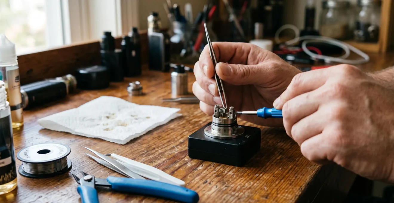
Atomiser build posts determine where coil leads can be secured, how the coil approaches the airflow and which installation techniques are practical. Their arrangement influences the usable coil diameter, lead orientation, mounting height and the space available for single- or dual-coil builds.
Two decks can accommodate the same resistance wire yet require entirely different mounting methods. Traditional posts provide defined attachment points, while postless terminals allow alternative positioning but often demand more precise lead preparation. Neither arrangement guarantees better heating or easier installation.
Understanding these differences helps prevent coils from being pulled out of alignment, leads from making incomplete electrical contact and excess wire from reaching unintended conductive surfaces. It also makes coil selection more predictable: a build must fit the deck mechanically, align with its airflow and remain electrically stable before its theoretical resistance becomes useful.
The practical starting point is therefore the physical deck, not a preferred wrap count or coil specification. All installation checks should be performed with appropriate tools and within the atomiser, mod and battery manufacturer’s operating limits.
Atomiser Build Posts: Key Installation Principles
- Post spacing, terminal orientation and airflow geometry jointly determine where a coil can sit; post spacing alone does not prescribe its inner diameter.
- Secure leads without transferring excessive tension into the coil, then verify stable resistance and clearance before use.
- Choose traditional or postless terminals according to wire geometry, clamping compatibility and the deck’s actual installation requirements.
- Why Does Build Post Placement Limit Where a Coil Can Sit on the Deck?
- How Can You Tighten Coil Leads in Build Posts Without Distorting the Coil?
- Postless or Traditional Build Posts: Which Deck Is Easier for Your Coil Style?
- Which Build Post Mistakes Can Cause Loose Coil Connections or Resistance Changes?
- How Can Pre-Trimming Coil Leads Simplify Installation on a Crowded Build Deck?
- How Can You Align Dual Coils for Balanced Heating and Airflow?
- Spaced or Contact Coil: Which Technique Better Fits Your Atomiser?
- Which Coil Configuration Best Matches Your Atomiser and Power Range?
Why Does Build Post Placement Limit Where a Coil Can Sit on the Deck?
Build post placement limits coil positioning because the terminals establish fixed locations for securing the leads. The coil must fit between or beside those terminals while maintaining sufficient clearance from the chamber and alignment with the intended airflow. Post spacing influences the usable coil diameter, but wire thickness, lead direction and deck geometry also determine what fits.
Consider two decks with different distances between their lead holes. A coil that mounts comfortably in one may require awkward lead bends in the other. Increasing its inner diameter can reduce the available clearance around the posts, while decreasing it may leave the leads approaching their terminals at difficult angles.
The relationship is geometric rather than a universal formula. Coil inner diameter, outer diameter and lead length are separate variables. A thicker wire also increases the coil’s external dimensions, even when the inner diameter remains unchanged.
On a traditional two-post deck, the terminal positions may naturally guide a coil toward the central airflow opening. Other two-post arrangements, including staggered or velocity-style designs, can place the coil differently depending on which holes are used and the direction of lead entry.
For a documented example, the Joyetech ProCore Remix deck specifications describe a staggered two-post RDA arrangement with bottom airflow, as well as a different postless arrangement in its RTA configuration. This illustrates how deck architecture and airflow placement vary even within one product family.
Lead entry direction matters just as much as hole spacing. A lead entering horizontally may allow a different coil height and rotation from one entering vertically. If the terminals pull the leads downward, the coil may tilt toward the deck floor instead of facing the air inlet.
Before securing either lead, insert the coil into its intended mounting position and inspect it from above and from the side. Check that the active wraps face the airflow, do not touch the deck or chamber and leave a suitable route for the wick.
Single-coil installation on a dual-coil deck needs particular attention. A coil placed geometrically in the middle of a deck originally designed for two coils may not align with either airflow outlet. Centering the coil between the posts is not necessarily the same as centering it over the air supply.
Depending on the device, possible solutions include a supported single-coil adapter, an alternative terminal pair, carefully planned asymmetric leads or a smaller coil that permits better positioning. Three-post decks may also offer alternative mounting arrangements. Any solution must be compatible with the specific atomiser.
Never compensate for unsuitable geometry by leaving leads unsecured or allowing the coil to contact surrounding metal.
Once a coil can sit naturally in the correct position, the next challenge is securing its leads without changing that geometry.
How Can You Tighten Coil Leads in Build Posts Without Distorting the Coil?
Coil leads can be tightened without distorting the wraps by supporting the coil throughout the clamping process, removing unnecessary lead tension and securing each terminal gradually. The objective is reliable electrical contact without allowing screw movement to drag the coil sideways, compress its wraps or change its intended position over the airflow.
A common installation problem occurs when the first lead is clamped while the coil is poorly positioned. Pulling the second lead taut then transfers force into the wrapped portion. Depending on the wire and the direction of the pull, this can stretch the coil, compress adjacent turns or tilt the entire assembly.
The most reliable mechanical approach is to keep a coil rod or suitable nonconductive positioning tool through the coil during installation. This supports the wraps and provides a reference for maintaining the desired height and angle.
- Position the unpowered, unwetted coil on its rod, with both leads correctly routed into their terminals.
- Lightly secure the first lead while supporting the coil. Avoid fully tightening against an obviously misaligned position.
- Adjust the coil until its wraps are correctly oriented relative to the airflow and the second lead enters its terminal without excessive pulling.
- Secure the second lead gradually, maintaining support with the coil rod. Finish tightening both terminals according to the manufacturer’s instructions.
- Remove the support, inspect all clearances and measure the cold resistance before any permitted heating check.
Mechanical positioning must be completed before applying power. An electrical pulse is not an appropriate method for repositioning a loose or unsecured coil.
Lead tension and screw tightness are different things. A terminal screw must hold the conductor securely, but tightening it harder does not correct poor lead routing. Excessive torque can damage threads, deform thin wire or shear softer materials such as nickel.
A secure terminal should prevent lead movement under gentle inspection without requiring maximum possible torque. Where a manufacturer specifies a tightening method or torque, that instruction takes precedence.
A pinch-and-release technique can help control the coil’s geometry: support the wrapped portion with an appropriate tool, tighten the terminal and release the support to see whether the coil moves. This is a mechanical operation performed without power. Metal tweezers must never contact an energised coil or create an electrical bridge between conductive parts.
If a previously trimmed lead no longer reaches its terminal properly, first check whether the coil can be repositioned within the deck’s permitted clearance. If a safe position cannot be achieved, replace or rebuild the coil with adequate lead length. Forcing a short lead beneath the edge of a screw head can produce incomplete contact.
After installation, measure resistance cold. Following the manufacturer’s permitted initial operating procedure and after the assembly has cooled, check the resistance again. An unexplained or unstable reading requires investigation before further use.
Correct tightening preserves the coil’s geometry, but the most suitable clamping technique still depends on the terminal design and the type of wire being installed.
Postless or Traditional Build Posts: Which Deck Is Easier for Your Coil Style?
Postless decks can simplify coil positioning when the leads are cut accurately and fit securely within their terminals. Traditional post decks often provide clearer visual references and can make some lead-routing tasks easier. The more convenient option depends on wire stiffness, conductor thickness, clamping geometry and the coil’s intended position rather than experience level alone.
Traditional posts generally secure the leads through holes, slots or under screw heads. Postless arrangements place their terminals closer to the deck surface and often require the coil legs to extend downward into receiving holes or slots.
The distinction is architectural, not absolute: both designs may use screws or clamps, and neither guarantees compatibility with every wire profile.
For instance, a thick composite wire may sit securely within a correctly sized clamp, while a thin round wire may require careful placement to prevent it from shifting as the terminal closes. Conversely, some traditional post screws can deform thin wire if they are overtightened.
The following decision grid describes practical tendencies rather than universal compatibility rules.
| Coil style | Traditional post deck | Postless deck |
|---|---|---|
| Round wire | Can provide straightforward lead placement and visible screw engagement; thin leads must not be sheared. | Can work well with correctly sized terminals, but thin leads may shift or deform in unsuitable clamps. |
| Clapton-style composite wire | Requires sufficient terminal capacity and an appropriate approach angle. | May accommodate thick leads conveniently in larger slots, provided the entire conductor is securely clamped. |
| Mesh | Ordinary round-wire posts are generally unsuitable unless specifically designed for mesh. | Requires purpose-built mesh clamps and a compatible wick-support arrangement; standard postless holes are not sufficient. |
Terminal compatibility matters more than the deck label. Mesh is the clearest example: a mesh-oriented atomiser typically uses broad clamping surfaces designed for strips rather than ordinary wire leads. A conventional postless deck should not be assumed to support mesh simply because it lacks raised posts.
A postless arrangement may give the builder useful freedom to position a coil above its air inlet, but that freedom is constrained by terminal entry direction, lead length and available chamber space. Some postless designs are highly prescriptive about coil height.
Traditional posts provide visible landmarks, making it easier to compare the coil’s position with the surrounding hardware. That does not guarantee correct airflow alignment, particularly on asymmetrical decks.
With postless designs, lead ends that extend too far through a terminal can potentially reach unintended conductive surfaces. The safe installation method is to follow the manufacturer’s specified lead length or trimming procedure, inspect the underside where accessible and confirm that no protruding wire can create an electrical short.
A practical comparison should therefore examine three things before choosing a deck: whether the terminal securely accepts the wire, whether the coil can reach its intended airflow position and whether excess lead material can be safely removed or contained.
Once the terminal type is appropriate, connection quality becomes the next priority because even a mechanically attractive installation can develop electrical instability.
Which Build Post Mistakes Can Cause Loose Coil Connections or Resistance Changes?
Loose coil connections and unexpected resistance changes can result from partially clamped leads, damaged terminals, overtightened screws, poor electrical contact or unintended contact between conductive components. Each fault affects the current path differently. Resistance readings can also vary with temperature, so an unstable connection must be distinguished from normal material behaviour before the atomiser is used.
A lead caught only beneath the edge of a screw may appear secure while making inconsistent contact. Movement or thermal expansion can then change the effective connection, potentially producing intermittent or fluctuating resistance readings.
Overtightening creates a different risk. Soft wire can be damaged or severed at the clamping point, while excessive force may strip the threads that retain the screw. Cross-threading can also prevent the terminal from reaching its intended clamping position.
Repeated rebuilding gradually increases the opportunity for mechanical wear. Rounded screw heads, visibly damaged threads and screws that no longer maintain normal engagement indicate that replacement parts or professional inspection may be needed.
Resistance readings require context. The resistance measured by a device can include the coil, leads and electrical contacts. It may also be influenced by instrument resolution, temperature and measurement conditions.
The Steam Engine coil-wrapping calculator models electrical resistance using wire properties, coil geometry and lead length. Its documentation also explains why real builds may differ from theoretical calculations because of physical and electrical effects.
Consequently, a difference between a calculated value and a measured value does not automatically identify a loose post. Nor does every difference between readings from two devices prove that the coil itself is defective.
For troubleshooting, compare resistance readings only under reasonably consistent conditions, especially with the coil cold. If a reading is unstable or changes unexpectedly, discontinue use, disconnect the power source and inspect the terminals and all possible contact points.
Do not use further heating as a diagnostic method when a defective connection or short circuit is suspected. There is no universal acceptable resistance-drift percentage applicable to all wires, meters and operating temperatures.
Residue also deserves attention. E-liquid deposits and other contamination can obstruct inspection or interfere with mechanical seating, although visible residue alone does not establish a measured increase in contact resistance.
The manufacturer’s Innokin coil-cleaning instructions describe removing the wick, inspecting the deck, cleaning visible residue and allowing components to dry completely. This is a maintenance procedure, not a guaranteed repair for damaged electrical contacts.
Five Checks Before Reusing a Rebuildable Deck
- Disconnect the atomiser from power and inspect both terminals; confirm that each intended lead is fully seated.
- Check screw engagement and visible lead condition; identify any damaged screw, thread or conductor requiring replacement.
- Remove visible residue using a compatible maintenance procedure; confirm that cleaned components are completely dry.
- Inspect coil and lead clearances with the chamber components fitted; confirm that no unintended metal contact is present.
- Measure cold resistance using an appropriate instrument; record the reading and resolve any unexpected instability before use.
These checks help separate mounting faults from calculation differences. If a terminal remains unreliable after correct reassembly, continuing to tighten it is not an adequate substitute for replacing damaged components.
Preventing connection problems also depends on lead preparation, especially when there is little room between terminals or beneath the coil.
How Can Pre-Trimming Coil Leads Simplify Installation on a Crowded Build Deck?
Pre-trimming coil leads can simplify installation by reducing excess wire inside a crowded deck and making terminal insertion more predictable. The correct length should be determined from the intended coil position and the terminal’s clamping requirements, not from a universal measurement. Cutting too short can make secure mounting impossible, while excessive length can create unwanted conductive contact.
A compact deck may provide little room for surplus leads. Long wire ends can interfere with coil alignment, obstruct access to terminal screws or approach neighbouring conductive surfaces.
Measuring the intended lead path before cutting helps prevent these problems without relying on an arbitrary length.
For a traditional post arrangement, first position the coil where it should ultimately sit and identify the route from each wrap end to the correct terminal. Mark the point at which the lead enters the usable clamping region, then allow sufficient material for full engagement and any manufacturer-specified trimming method.
This is a planning measurement, not necessarily the final cut location. Some terminals are designed to accept and secure long leads before the excess is removed; others require accurately trimmed leads before insertion.
On a deck that permits trimming after clamping, it can be useful to secure and align the first lead before determining the final length of the second. This uses the actual installed geometry rather than an estimated distance.
However, pre-trimming is not automatically preferable. Postless decks may require both leads to be cut to predetermined lengths because the coil drops vertically into its terminals. In those designs, trimming one lead after installation may not be possible or advisable.
The route also matters. Leads may need to pass beside an airflow structure, avoid the edge of a liquid well or approach a terminal from a particular direction. A straight-line measurement can underestimate the required length when an obstacle changes the path.
For this reason, trace the entire lead route before cutting. Leave only the amount of wire needed for secure terminal engagement and the specified installation process.
If a lead has already been cut too short to engage securely, do not trap its tip beneath a screw or extend it with an improvised connection. Replacing the coil or preparing a new lead arrangement is the safer corrective action.
After trimming, inspect all cut ends, particularly in terminal designs where they may protrude beneath the deck. Also check that no offcut remains loose inside the atomiser.
Finally, reinstall the chamber without power and ensure that the coil remains clear of surrounding conductive surfaces. A position that appears safe on an exposed deck may not provide adequate clearance once the atomiser is fully assembled.
With the lead paths established, dual-coil installations introduce another consideration: the two assemblies must remain appropriately positioned relative to one another and to their airflow outlets.
How Can You Align Dual Coils for Balanced Heating and Airflow?
Dual coils are aligned by matching their intended geometry, mounting height and relationship to the airflow, while ensuring that each has secure electrical connections. Comparable coils connected in parallel should have similar electrical characteristics, but matching resistance alone does not guarantee identical heating or wicking. Both the electrical arrangement and the physical installation must be checked.
Deck architecture determines how much freedom is available. On a four-post design, each coil may have a separate pair of terminals, making adjustment comparatively independent.
On a two-post deck with shared terminals, both coils may need to enter the same posts or clamps. The builder must maintain secure engagement for every lead without allowing the terminal to displace one coil while securing the other.
The geometry should be checked from two viewpoints:
- From above, compare the horizontal position of each coil relative to its intended airflow opening and surrounding posts.
- From the side, compare coil height, tilt and clearance from the air inlets, deck floor and chamber.
Matching lead lengths can simplify symmetrical mounting, but mechanical symmetry does not eliminate electrical differences caused by wire tolerances, imperfect connections or different effective conductor lengths.
For two identical coils wired in parallel, the combined resistance is half that of either individual coil. This is an electrical relationship, not evidence that both installed coils are making equally reliable contact.
If the completed installation produces an unexpected resistance reading, check the cold electrical connections before attempting any heating test. A coil that is visibly tilted or mounted at an unsuitable height should also be repositioned with power disconnected.
When the manufacturer’s procedure permits controlled initial heating, it may help reveal unequal heating patterns in compatible power-mode materials. This should be performed only after the installation has passed resistance and clearance checks, using appropriate equipment and the specified procedure. Bare Ni200 and other materials requiring temperature control should not be treated like conventional dry-fired power-mode wire.
A coil that begins heating differently from its partner does not identify one unique fault. Possible explanations include electrical differences, contact problems or geometry variations. Airflow imbalance, meanwhile, becomes most relevant during actual airflow-dependent operation and cannot be diagnosed from glow timing alone.
Wicking introduces an additional distinction. Two coils that behave similarly before wicking may operate differently if one wick is tighter, receives less liquid or is positioned differently within its liquid channels.
Each wick should therefore be installed according to the atomiser’s design, fully saturated before operation and assessed under the manufacturer’s appropriate starting conditions. Unequal liquid delivery should not be corrected simply by increasing power.
Once both coils are correctly mounted, the spacing between individual wraps becomes another variable affecting installation and heating behaviour.
Spaced or Contact Coil: Which Technique Better Fits Your Atomiser?
A spaced coil has deliberate gaps between adjacent wraps, while a contact coil is wound with neighbouring turns touching or nearly touching. Both can suit compatible rebuildable atomisers, but their behaviour depends on wire material, gauge, resistance and mounting tension. Spaced coils reduce reliance on wrap-to-wrap contact, whereas contact coils require more consistent wrap geometry and appropriate preparation.
The choice should begin with material compatibility and the atomiser’s intended operating mode. A technique suitable for conventional power-mode resistance wire should not automatically be applied to temperature-control materials.
Contact coils are often used where a compact wrapped section is useful. Their adjacent turns can interact electrically and thermally, and their heating pattern may depend on the consistency of those contacts.
Spaced coils deliberately separate each turn. This can reduce direct contact between neighbouring wraps, but gaps still need to be reasonably consistent, and the coil must remain within the available deck space.
Post tension affects both designs. If the terminals pull unevenly on the leads, a contact coil can stretch or compress, changing how its wraps touch. A spaced coil may better preserve intentional separation under minor positioning changes, although excessive tension can still distort its spacing and overall shape.
Wire gauge also influences the choice. Thicker wire occupies more space and may require different wrap geometry to achieve a suitable resistance, while thinner wire can be easier to deform during installation. Composite wire introduces additional physical dimensions and behaviour that should be considered separately.
Any heating-pattern assessment must respect the wire’s material and the device manufacturer’s instructions. Controlled adjustment of compatible conventional power-mode coils can sometimes address localised heating irregularities, but a glow pattern is not a universal test of safe installation.
Contact coils may develop localised hot spots when neighbouring wraps or lead connections behave unevenly. Spaced coils can also show irregular heating if the wraps, terminals or lead lengths are inconsistent.
For either construction, unexpected resistance readings or suspected shorts take priority over attempts to improve the glow pattern. Power must be disconnected before mechanical adjustments, and conductive tools must not bridge live components.
With temperature-control wire such as Ni200, resistance behaviour is particularly important because the device uses resistance changes to estimate temperature. Keeping wraps separated can help avoid unintended turn-to-turn electrical contact, but it does not make an otherwise unsuitable build safe.
Follow the device’s approved wire materials, operating mode, installation procedure and resistance range. Do not dry-fire bare Ni200 as though it were a conventional power-mode coil.
The best practical choice is therefore the construction that remains mechanically stable, electrically compatible and properly aligned within the particular atomiser.
Wrap spacing is one part of the final selection. The complete configuration must also match the deck’s mounting capacity and the power available from the device.
Key Takeaways Before Choosing a Coil Configuration
- Measure physical clearance and confirm terminal compatibility before selecting wire dimensions or a target resistance.
- Treat electrical resistance, heat behaviour and airflow positioning as separate design constraints that must all be satisfied.
- Consider installation complexity, wicking requirements and maintenance effort alongside the desired operating range.
Which Coil Configuration Best Matches Your Atomiser and Power Range?
The best coil configuration fits the atomiser’s terminal geometry, chamber clearance and airflow design while remaining within the mod and battery manufacturer’s electrical limits. Wire material, gauge, wrap count and the number of coils should be selected together. A theoretically suitable resistance is not enough if the leads cannot be mounted securely or the coil cannot occupy its intended position.
Begin with the deck’s physical constraints. Establish whether it supports single coils, dual coils or another manufacturer-approved heating element. Check the maximum practical coil dimensions, available terminal capacity and the relationship between the mounting points and the air inlets.
Next, identify the supported wire materials and operating modes of the device. A temperature-control build must use compatible materials and settings, while a power-mode build must remain within the equipment’s stated operating limits.
Resistance calculations can then help narrow the possible combinations of material, wire cross-section, coil diameter, lead length and wrap count. The result must always be checked against the completed installation rather than treated as a guaranteed measurement.
Resistance and power are related but not interchangeable. Two configurations can receive similar total electrical power while distributing heat across different amounts of wire surface. Their heating response may therefore differ even when the power setting is the same.
In a regulated device, the mod’s supported voltage, current, resistance and wattage ranges constrain the possible combinations. A low-resistance build does not automatically require maximum power, and a higher-resistance build is not automatically compatible with every device.
For mechanical or unregulated devices, battery current capability and the complete circuit become particularly important. Those configurations require specific electrical knowledge and should not be selected from a generic resistance recommendation.
The selection can be organised around four practical criteria:
- Confirm the deck’s intended coil count, compatible terminal dimensions and available clearance.
- Select a wire material and operating mode explicitly supported by the device.
- Estimate the coil geometry and resistance, accounting for conductive lead length as well as the wrapped portion.
- Verify that the physical installation and measured resistance satisfy the manufacturer-specified limits before use.
A single-coil setup may require fewer leads and a simpler wicking arrangement. A dual-coil setup introduces additional terminals or shared connections, more wick material and a need to position two heating elements consistently.
Dual coils may also increase liquid consumption and battery demand depending on the chosen power, coil construction and usage pattern. The difference is not determined by coil count alone.
Rebuild frequency deserves consideration. Larger or more complicated coil assemblies can demand more preparation and maintenance, while a straightforward single-coil configuration may be more convenient for users who frequently replace wicks or experiment with different builds.
No configuration is universally preferable. The most useful arrangement is the one that can be installed correctly, operates within the approved electrical range and delivers consistent performance without unnecessary rebuilding complexity.
For the next build, inspect the empty deck first, plan the lead routes and airflow position, calculate the proposed resistance, then verify the completed installation cold before following the manufacturer’s operating procedure. This sequence makes coil selection a controlled compatibility decision rather than a matter of trial and error.
Can two coils with the same resistance fit differently on the same deck?
Yes. Two coils can have similar electrical resistance but different inner diameters, wire thicknesses, wrap counts or lead lengths. Those differences affect the space required and the angle at which their leads approach the terminals. Resistance alone cannot establish mechanical compatibility.
Should coil resistance be measured before or after trimming the leads?
The completed, securely clamped and trimmed installation should be measured cold before use. Calculating resistance before installation is useful for planning, but the final measured value reflects the actual conductive assembly and its connections.
Does a postless deck always require a coil-leg cutting tool?
No. A dedicated cutting guide may improve repeatability on designs requiring predetermined leg lengths, but some atomisers provide their own measurement instructions or allow alternative preparation methods. The essential requirement is the correct length and secure engagement for the particular terminal arrangement.
Can a loose build post be repaired simply by tightening its screw?
Only if the issue is an insufficiently tightened, otherwise undamaged connection and the manufacturer’s tightening procedure resolves it. Damaged threads, worn screws, unsuitable wire or incorrectly seated leads require separate corrective action. Repeatedly applying greater torque can worsen mechanical damage.
Why might a coil fit the exposed deck but contact the atomiser after assembly?
The chamber, chimney or airflow components may occupy space that is not apparent when the deck is exposed. The coil’s outer diameter, height, lead ends and any movement during tightening must all be considered. Check clearances with the relevant components fitted and without power before operating the atomiser.