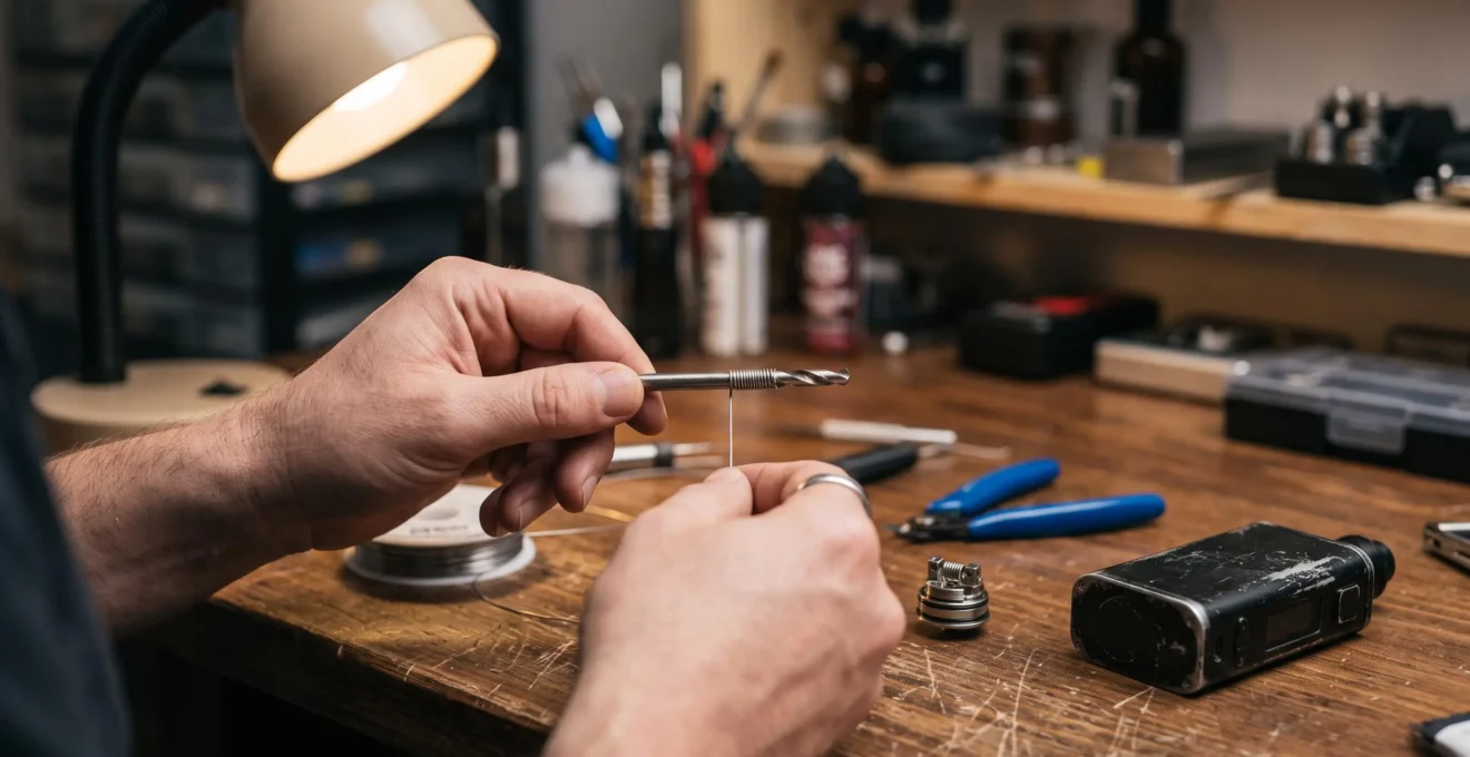
Consistent rebuildable coils start with controlled geometry rather than repeated wattage adjustments. Using the same wire specification, mandrel diameter, wrap count and installation position makes each build easier to reproduce. Secure electrical connections and stable resistance measurements then help identify whether the installed coil matches the intended design.
The challenge is that winding accuracy alone does not guarantee consistent heating. Tightening a post screw can pull a coil off-axis, lead trimming changes the electrical path, and an apparently symmetrical dual-coil installation may still receive uneven airflow or liquid supply. Each stage introduces variables that need separate checks.
For experienced builders, the most useful approach is to establish fixed references, inspect the finished geometry, measure resistance with suitable equipment and follow the atomiser and device manufacturers’ compatibility requirements. Thermal behaviour also depends on wire material, mass, power delivery and liquid saturation. A visually tidy coil is therefore a starting point, not proof of electrical safety or controlled aerosol temperatures.
Building more consistent rebuildable coils
- Use a fixed-diameter mandrel, repeatable wire tension and matching wrap counts to reproduce coil geometry.
- Protect the coil from lead distortion, unintended electrical contact and movement during installation.
- Verify stable resistance and mechanical clearance before use; choose power settings according to the complete build and device specifications.
- Why Do Uneven Coil Wraps Make Rebuildable Heating Less Predictable?
- How Can You Wrap a Consistent Coil Without Distorting the Wire?
- Spaced or Contact Coil: Which Technique Better Fits Your Atomiser?
- Which Coil-Building Errors Can Cause Resistance to Shift After Installation?
- In What Order Should You Install and Check a Rebuildable Coil?
- How Can You Align Dual Coils for Balanced Heating and Airflow?
- How Can You Tighten Coil Leads in Build Posts Without Distorting the Coil?
- How Does Electrical Resistance Affect Power and Heating in a Vape Coil?
Why Do Uneven Coil Wraps Make Rebuildable Heating Less Predictable?
Uneven coil wraps make heating less predictable because they alter the distribution of wire, contact points and thermal mass around the coil. Compressed turns, overlapping wire and deformed sections can create localised heating differences. However, unequal spacing alone does not prove that a hot spot exists or that electrical resistance has changed significantly.
A properly formed coil follows a consistent path around its mandrel. For a spaced configuration, adjacent gaps should be reasonably uniform. For a contact configuration, neighbouring turns should maintain their intended alignment without crossing or damaging one another. A minor cosmetic difference is not necessarily a functional defect, but pronounced distortion deserves investigation.
Look for three structural warning signs before installation:
- Overlapping or kinked wraps: These can introduce unintended electrical contact or locally deform the conductor.
- A tapered or conical profile: A changing coil diameter can affect positioning, clearance and the relationship between the heating surface and wick.
- Unequal or distorted leads: Different lead paths can affect final conductor length and pull the coil away from its intended position.
Changing the gaps between otherwise identical turns does not automatically produce a large resistance change. The relevant electrical quantity is the actual conductive path. A wrap that shifts far enough to change the path or create an unintended contact can produce a different result from a wrap that is merely spaced imperfectly.
The distinction matters when troubleshooting. Increasing wattage to compensate for apparently weak heating does not correct a poor electrical connection, a damaged winding or insufficient liquid delivery. It may instead increase the thermal stress imposed on the build.
A repeatable inspection should compare the current coil with its intended diameter, turn count, shape and installed lead configuration. Resistance is then a complementary measurement rather than a substitute for visual examination.
Once the intended geometry is established, the next priority is reproducing it without adding distortion during winding.
How Can You Wrap a Consistent Coil Without Distorting the Wire?
Wrap a consistent coil by selecting a fixed-diameter mandrel, keeping the wire aligned and applying controlled tension throughout the winding process. Reproduce the same number of turns, wire material and lead orientation for comparable builds. The objective is stable geometry without stretching, sharply bending or damaging the conductor.
A correctly sized drill bit, smooth screwdriver shaft or dedicated coil jig provides a repeatable reference for internal diameter. A coil jig can also guide successive turns, while a plain mandrel offers direct control over spacing. Whichever tool is selected, its diameter should remain consistent between builds.
Wire supplied directly from a spool can provide steady feed tension and reduce unnecessary handling. Pre-cut wire is equally workable when its length is sufficient for controlled winding and lead positioning. Neither approach guarantees better results: the condition of the wire and the builder’s control matter more than the packaging format.
A practical winding routine follows a consistent sequence:
- Confirm the wire material, gauge and intended compatibility with the device’s operating mode.
- Choose a known mandrel diameter and keep the mandrel steady.
- Guide the wire around the mandrel under moderate, even tension without pulling hard enough to deform it.
- Count turns consistently, including the chosen convention for full or half wraps.
- Inspect the resulting shape and lead direction before removing the coil from its support.
Thin wire may deform under excessive tension, while thicker wire generally requires more controlled mechanical force to bend evenly. Springback also varies with material and wire construction. Avoid trying to remove every irregularity by repeatedly bending the same section, particularly when its surface is visibly damaged.
Heat treatment or annealing can change how some wires retain their shape, but it should not be treated as a universal preparation technique. Wire materials differ in temperature limits, surface chemistry and suitability for dry heating. Follow the relevant manufacturer’s guidance instead of assuming that heating a bare coil is always appropriate.
The Steam Engine coil-wrapping calculator provides a useful geometrical reference. Its inputs include wire properties, coil diameter, number of wraps and lead dimensions. The result is an estimate, not a replacement for measuring the assembled coil.
After producing a repeatable winding, the next decision is whether its turns should be spaced apart or deliberately arranged in contact.
Spaced or Contact Coil: Which Technique Better Fits Your Atomiser?
Neither spaced nor contact coils are universally more consistent. Spaced coils separate adjacent turns, while contact coils place them together. The better choice depends on wire material, deck clearance, airflow, wicking arrangements and device compatibility. Repeatable geometry and sound electrical connections matter more than the label assigned to the winding style.
Thermal expansion affects both configurations. In a spaced coil, individual gaps can change as the wire expands and cools. Contact arrangements introduce neighbouring surfaces that may interact mechanically and electrically. Neither construction eliminates the need to inspect the finished installation.
Wire structure adds another variable. A simple round wire is easier to inspect visually than a complex composite. Clapton-style wire, with a fine outer winding around a core, introduces additional surface area and spaces where residue may accumulate. That does not establish a universal preference for either contact or spaced winding.
The following comparison focuses on practical selection criteria rather than unsupported performance rankings.
| Criterion | Spaced coil | Contact coil |
|---|---|---|
| Geometry | Requires controlled gaps between turns | Requires consistent alignment of neighbouring turns |
| Deck clearance | May require more axial space for the same wrap count | Can provide a shorter winding length when turns sit together |
| Inspection | Individual gaps and wire paths are generally visible | Interfaces between adjacent turns require attention |
| Frequent rebuilding | Repeatable when spacing is reproduced reliably | Repeatable when winding contact and alignment are controlled |
| Complex wire | Spacing must suit the composite wire structure | Turn contact and possible residue accumulation need consideration |
| Flavour performance | Depends on the complete heating and liquid-delivery system | Also depends on the complete system, not turn contact alone |
Atomiser geometry may settle the choice. A narrow chamber can restrict the available winding length, while an airflow inlet positioned beneath a coil imposes different placement requirements from side airflow. The wick must also fit the intended coil diameter without excessive compression or inadequate contact.
In a 2020 experimental study of contact and non-contact vape coils, researchers tested Kanthal and nichrome configurations under different electrical and liquid conditions. Coil temperatures varied substantially with the test environment. The findings support treating coil temperature as a system-dependent outcome rather than a property determined by spacing alone.
Experimental comparison of coil configurations
Mulder and colleagues examined contact and non-contact coils made from Kanthal and nichrome, applying four voltages and comparing dry conditions with coils saturated in pure vegetable glycerin or propylene glycol.
Reported temperatures exceeded 1,000°C under dry test conditions and remained below 300°C in the liquid-saturated conditions examined. These figures apply to the tested experimental arrangements and are not universal temperatures for rebuildable atomisers. The study also investigated changes in coil metals after repeated heating cycles.
A useful selection method is to choose a configuration that physically fits the deck, matches the intended wire specification and can be reproduced reliably. Flavour density or rebuilding speed should not be assigned universally to either style without device-specific evidence.
Once the winding style is chosen, consistency depends on preserving its electrical path when the coil is secured to the deck.
Which Coil-Building Errors Can Cause Resistance to Shift After Installation?
Resistance can shift after installation when the conductive path changes, terminal contact becomes unreliable or measurement conditions vary. Common mechanical causes include loose posts, moving leads, damaged wire and unintended contact between conductors. A difference between calculated and installed resistance is not automatically a fault, but unstable readings require investigation before firing.
Several problems can appear during or immediately after mounting:
- Crossing or touching leads: Unintended contact may create a shorter electrical path or an electrical short.
- Movement during tightening: A rotating lead can pull the winding and change its installed geometry.
- Incomplete terminal contact: A poorly secured conductor can introduce variable contact resistance.
- Damaged or partially severed wire: Mechanical damage may compromise electrical continuity and reliability.
Trimming excess leads changes the amount of conductor in the circuit when that excess forms part of the original conductive path. A resulting resistance difference may therefore be expected. In contrast, readings that fluctuate when the assembly is gently repositioned or after temperature has returned to its previous state can indicate a connection or measurement problem.
Resistance should be compared under consistent conditions. Record a baseline after securing the coil, check again after final positioning and trimming, and compare subsequent readings only when the build has returned to a comparable temperature. Stop if resistance becomes unstable, the device reports a fault or the coil shows unintended contact.
A 2020 study on electronic-cigarette coil resistance measurement demonstrated that the measurement method can influence reported resistance. Its two-wire laboratory configuration produced a positive measurement bias of 0.086 ohms, while a four-wire configuration was less susceptible to that bias.
0.086 Ω
Positive measurement bias reported for a two-wire configuration in a laboratory study of commercial pod-style electronic-cigarette assemblies. This is not a universal error allowance or acceptable resistance variation for rebuildable coils.
Saleh, Hensel and Robinson, International Journal of Environmental Research and Public Health (2020).
The practical implication is that a resistance mismatch should be interpreted alongside measurement equipment, connection quality, temperature and the expected design. A stable reading cannot prove that every part of a build is mechanically correct, just as a small difference does not independently establish a short circuit.
On a fixed-voltage device, a reduction in resistance increases current and electrical power, assuming the applied voltage remains the same. On a regulated wattage device, the control electronics behave differently and have their own operating limits. In both cases, a questionable build should be corrected rather than compensated for with power adjustments.
A consistent installation sequence makes these mechanical faults easier to prevent and detect.
In What Order Should You Install and Check a Rebuildable Coil?
Install a rebuildable coil by confirming component compatibility, positioning the winding with its geometry supported, securing both leads, trimming excess wire and checking electrical stability before use. Verify that the coil cannot touch unintended conductive surfaces. Any optional heating check must follow the wire and device manufacturers’ instructions rather than a universal dry-firing routine.
Begin with the atomiser disconnected from its power source. Examine the deck, screws, insulators and terminal openings for visible damage or debris. A damaged insulator or unreliable terminal is a reason to stop rather than attempt a compensating winding adjustment.
Support the coil on its mandrel while positioning it relative to the intended airflow. The mandrel can help preserve diameter and alignment as the leads are introduced into the posts. Secure one lead enough to retain its position, then secure the second without forcing the winding off-axis. Finish tightening as appropriate for the terminal design and inspect both connections before trimming.
The important distinction is between securing the electrical connection and applying unnecessary tension to the winding. A lead should not remain loose inside its terminal, but excessive pulling can transfer force directly into the first or last turn.
Only trim protruding leads after their positions are established. Inspect the resulting cut ends, particularly near a chamber wall or another conductive component. Very small pieces of wire left in the deck can create an unintended conductive path.
Some traditional rebuilding guides describe brief low-power pulses and visual inspection of the coil’s glow. For compatible contact-wire builds, an irregular glow may indicate localised heating or an unintended electrical interaction. A centre-outward glow is a commonly described observation, not a universal acceptance criterion. Spaced coils and different alloys may behave differently.
Dry firing can expose wire to substantially different thermal conditions from normal liquid-saturated operation. Bare-coil pulsing, glowing and mechanical adjustment should therefore never be assumed suitable for every alloy, especially wires intended for particular temperature-control modes. Do not touch or manipulate an energised coil with conductive tools, and allow it to cool before handling.
Five checks before accepting a completed coil
- Confirm compatibility: Record the wire specification and verify that the atomiser and device permit the intended configuration.
- Inspect positioning: Confirm that the winding remains centred as intended, retains its diameter and has adequate clearance from surrounding metal.
- Verify terminal security: Confirm that both leads are properly retained and that no excess conductor or wire fragments remain in the deck.
- Measure resistance: Record the assembled coil’s cold resistance and compare it with the expected value and device limits.
- Complete the final inspection: Confirm stable readings and appropriate wick placement, documenting any discrepancy that requires rebuilding before use.
Once the electrical installation is accepted, fit the wick according to the atomiser’s design. Wicking pressure, liquid saturation and airflow can affect operating temperature even when the resistance remains unchanged. Initial power settings must remain within the device’s supported operating conditions; low power is not a substitute for verifying electrical safety.
The sequence becomes more demanding when two coils must operate together, because both electrical matching and airflow symmetry need attention.
How Can You Align Dual Coils for Balanced Heating and Airflow?
Balanced dual-coil builds require matching electrical characteristics, closely reproduced winding geometry and symmetrical positioning relative to the deck’s airflow. Two coils with identical nominal resistance may still operate differently when their lead paths, airflow exposure or wicking conditions differ. A consistent dual build therefore requires checking the complete pair rather than resistance alone.
Start by using the same wire material, gauge and construction for both coils. Wind them on the same mandrel, applying the same turn-count convention and intended spacing. Compare the finished windings visually before installation, including their overall length, diameter and lead orientation.
When the circuit places two identical coils in parallel, the combined resistance is half the resistance of either individual coil. This relationship assumes the coils have equal resistance and are connected in the intended parallel configuration. Different deck designs and connection arrangements must be assessed separately.
If individual coil resistances differ significantly, investigate the physical construction and measurement conditions instead of assuming that their combined resistance is sufficiently close to the target. Adjustments to wrap count alter conductor length but can also change heating surface and coil mass. Matching should therefore be planned before the coils are secured, rather than achieved through improvised changes to an installed winding.
Position both coils with comparable clearance from airflow inlets and nearby metal. Symmetry should be judged against the actual chamber geometry, not merely the distance between the coils. In some decks, equal exposure depends on mounting height as well as horizontal placement.
After installation, inspect and measure the assembled pair with the device unpowered. Where a deck and suitable measurement arrangement allow genuinely independent coil measurements, these can help isolate a discrepancy. Avoid disconnecting or manipulating conductors while the device is powered. Visual heating tests, where expressly compatible with the materials and equipment, remain supplementary rather than proof of balanced operation.
Wicking introduces another source of asymmetry. Two geometrically identical coils can receive liquid at different rates when wick density, tail length or placement differs. Unequal saturation may cause one side to behave differently despite apparently matched resistance.
Even carefully matched windings can become unequal during mounting, particularly when terminal screws transfer force into their leads.
How Can You Tighten Coil Leads in Build Posts Without Distorting the Coil?
Tighten coil leads without distortion by supporting the winding, controlling lead position and using a screwdriver that fits the terminal correctly. Apply only the force required for a secure connection under the manufacturer’s instructions. Excessive torque can rotate a lead, pull the winding off-axis, damage softer wire or compromise the post itself.
The principal mechanism is force transfer. As a screw presses on the conductor, friction or deformation can move the lead. If the wire between the terminal and winding is under tension, that movement may reach the nearest wrap and disturb the coil’s geometry.
Keeping a correctly sized mandrel inside the winding during installation helps resist this movement. Hold the mandrel steady without levering against the deck. Control the lead’s position while the screw engages, then inspect whether tightening has displaced the winding.
Lead slack requires judgement. Leaving enough free conductor to avoid pulling the coil directly against a terminal can protect its shape during initial positioning. Too much slack, however, may create unwanted bends, obstruct airflow or introduce additional clearance problems. Wide post spacing, compact decks and angled terminals each impose different mechanical constraints.
A correctly fitting screwdriver reduces the risk of slipping or damaging the screw head. Tightening should stop at the manufacturer’s specified torque, when available, or at the appropriate secure contact described in the device instructions. Attempting to make an already secure connection tighter can strip threads, deform the conductor or damage the terminal.
After securing both leads, inspect the coil from more than one direction. A tilted winding, displaced end wrap or newly uneven lead angle may indicate that tightening has transferred force into the coil. Confirm that the leads remain seated and that the winding clears every unintended conductive surface.
Finally, compare the assembled resistance with the expected value under stable measurement conditions. An unexpected difference does not identify the faulty component by itself, but it is reason to recheck the connection and geometry before proceeding.
With the geometry and terminal connections established, electrical resistance provides one final quantitative reference for comparing builds.
Key takeaways before choosing power settings
- Resistance is meaningful only when the wire material, diameter, conductor length and circuit configuration are understood.
- Matching resistance values do not guarantee matching heat capacity, surface area or liquid delivery.
- Unexpected resistance or unstable measurements should trigger inspection, not automatic compensation through wattage.
How Does Electrical Resistance Affect Power and Heating in a Vape Coil?
Coil resistance affects electrical current and power delivery, but its practical effect depends on how the device regulates its output. At a fixed voltage, lower resistance produces higher current and greater electrical power. At a fixed regulated wattage, the device adjusts voltage and current, so lower resistance does not inherently mean greater heating power.
For a resistive load, Ohm’s law relates voltage, current and resistance. Electrical power can be expressed as voltage multiplied by current, or as voltage squared divided by resistance. These relationships describe electrical input; actual coil temperature also depends on heat capacity, heat loss, airflow and liquid saturation.
With an ideal constant-power output, decreasing resistance means the required voltage decreases while the required output current increases. A fixed-voltage device behaves differently: reducing resistance increases both current and power. Real regulated devices have voltage, current and resistance limits that can constrain either behaviour.
Resistance is partly determined by the conductor’s material resistivity, cross-sectional area and total electrical length. Using the same wire type and gauge, a repeatable number of wraps, winding diameter and installed lead length provides a useful basis for comparing builds.
However, two coils can share the same resistance while having different geometries. A build with thinner wire and fewer turns might reach a similar resistance to one made with thicker wire and more turns. Their surface areas, thermal masses and heating and cooling responses need not match.
This difference is particularly relevant to complex wires and multi-coil configurations. Added conductor mass may change heat capacity, while parallel electrical paths change combined resistance. A target resistance is consequently a design constraint rather than a complete description of heating behaviour.
Before use, compare the device’s displayed resistance against the intended value and a reliable measurement of the assembled build. Allow for measurement conditions and the manufacturer’s stated accuracy, but do not treat unexplained variation as harmless. Inspect terminals, leads, coil clearance and circuit configuration whenever the values are inconsistent.
Choosing wattage should follow verified compatibility with the device, wire and atomiser, together with the manufacturer’s operating guidance. There is no universal wattage or resistance threshold that makes every rebuildable coil appropriate for every setup.
For the next rebuild, record the wire specification, mandrel diameter, wrap count, measured cold resistance and final coil position. Keeping those details consistent creates a useful reference for identifying genuine deviations without treating resistance as the only measure of build quality.
Can two coils with the same resistance produce different heating behaviour?
Yes. Coils with matching resistance can differ in wire mass, surface area, material, winding geometry and airflow exposure. These factors influence heating and cooling even when the measured electrical resistance is identical. Resistance should be assessed alongside the complete coil design.
Should a new rebuildable coil match a calculator’s predicted resistance exactly?
Not necessarily. Calculators estimate resistance using selected wire properties and geometry, while the installed build has real lead lengths, contact conditions and measurement uncertainty. Compare the measured value with the predicted result and investigate differences that cannot be explained by the design or measurement conditions.
Does a coil have to glow from the centre outward to be correctly built?
No. Centre-outward glowing is a conventional visual check described for some compatible contact-coil builds, not a universal rule for every wire material or winding arrangement. Dry heating can expose the conductor to substantial thermal stress, and some materials should not be dry-fired. Electrical stability, physical clearance and manufacturer compatibility remain essential.
Can resistance change because a coil is warm rather than mechanically defective?
Yes. Electrical resistivity can vary with temperature, and the amount and behaviour of that variation depend on the conductor material. Compare resistance readings at similar temperatures. Persistent unexplained changes or fluctuating connections still require investigation before the device is used.
When should a distorted coil be replaced instead of adjusted?
A winding with visibly damaged conductor, severe kinks, compromised leads or persistent electrical instability should not be accepted merely because its resistance falls near the target. Replacing the damaged wire and rebuilding to the intended geometry is more appropriate than repeatedly forcing a compromised coil into shape.