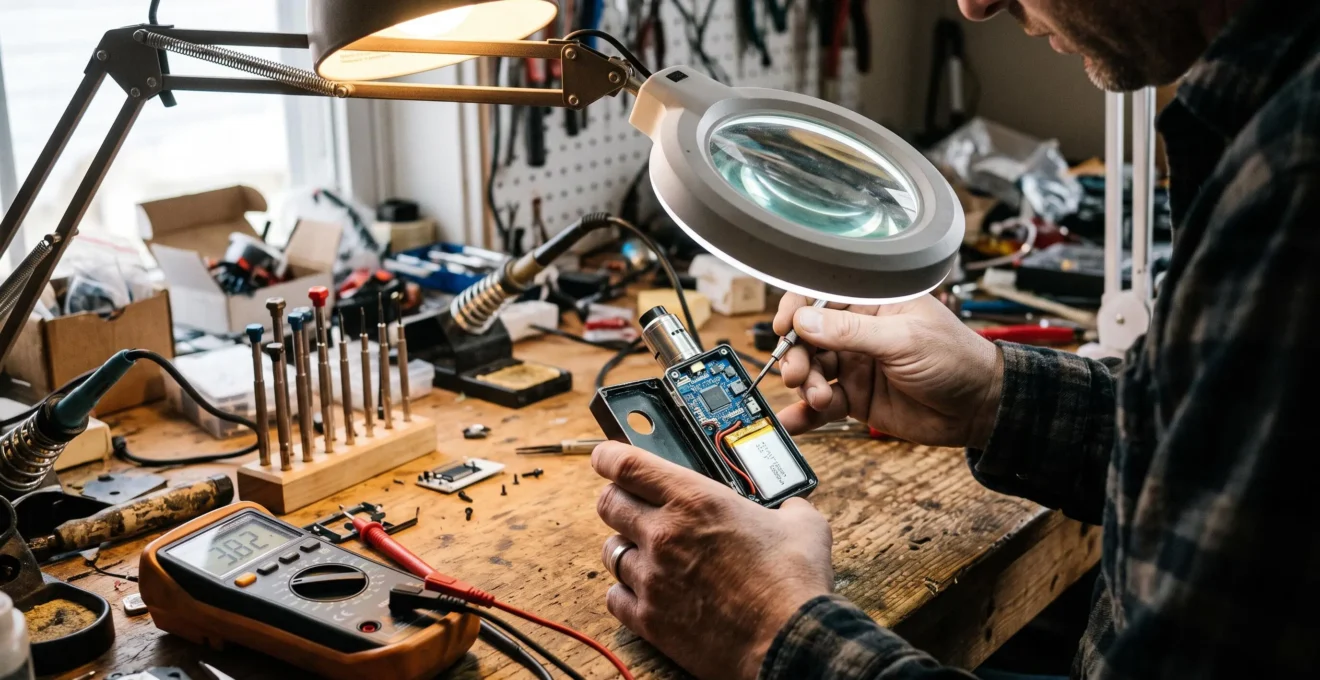
A regulated vape device does not simply connect its battery to a heating coil when the user presses a button. An integrated control microchip processes electrical measurements, interprets the selected operating mode and coordinates the power circuitry responsible for heating the atomizer.
The controller uses information such as battery voltage, atomizer resistance and available temperature-related signals to determine whether heating can begin and how the output should be managed. During operation, it can adjust power delivery, monitor electrical limits and interrupt heating when a protection condition is detected.
This processing layer explains why two devices with similar batteries and coils can behave differently. Converter architecture, measurement accuracy, firmware logic and protection thresholds all influence the final output.
Understanding these functions also makes troubleshooting more reliable. A resistance warning, unexpected power reduction or interrupted puff does not automatically mean the microchip has failed. The same symptoms can arise from device settings, electrical connections, atomizer components or battery conditions.
How regulated vape control chips work: key points
- A control chip interprets voltage, resistance and temperature-related measurements before and during heating.
- Power regulation depends on electronic switching, conversion circuitry and feedback, not simply the wattage shown on the screen.
- Unexpected device behaviour should be assessed through settings, connections, atomizer condition and battery status before suspecting controller failure.
- Why Does a Vape Microchip Monitor Voltage, Resistance and Temperature Signals?
- How Does a Vape Chip Translate a Power Setting Into Coil Output?
- Basic or Advanced Vape Chip: Which Functions Matter for Everyday Use?
- Which Symptoms Can Indicate a Vape Control Chip Is Not Operating Normally?
- When Should You Check Device Settings Before Blaming the Vape Microchip?
- How Does a Vape Circuit Board Process a Puff From Button Press to Heating?
- How Can You Interpret Vape Screen Data Without Focusing on a Single Number?
- How Can Real-Time Vape Device Telemetry Help Diagnose Hardware Behaviour?
Why Does a Vape Microchip Monitor Voltage, Resistance and Temperature Signals?
A vape microchip monitors battery voltage, atomizer resistance and temperature-related information because these measurements describe the electrical conditions under which heating occurs. Together, they help the controller determine whether the attached coil is compatible, whether sufficient battery power is available and whether the device should regulate, reduce or interrupt its output.
Battery voltage indicates the electrical supply available to the power-conversion stage. The controller must account for voltage changes under load and enforce the battery-related limits established by its hardware and firmware.
Atomizer resistance is essential for interpreting the electrical load. When an atomizer is attached, a compatible controller can establish a baseline resistance reading. That value may subsequently change as the heating element warms or as electrical contact conditions vary.
The distinction between cold and heated resistance becomes particularly important in temperature-control mode. With compatible heating materials, the controller uses the relationship between resistance and temperature to estimate coil temperature rather than relying on a dedicated sensor embedded in the heating wire.
The Evolv DNA 250C technical datasheet documents this resistance-based approach. It also explains why attaching an already-hot atomizer can lead to an incorrect temperature estimate until the atomizer cools.
Temperature monitoring operates through two different mechanisms. In active temperature control, the controller estimates coil temperature and adjusts output to respect a selected limit. In passive thermal protection, a sensor may instead monitor the circuit board or another component and trigger a protective response when its threshold is reached.
These mechanisms are not interchangeable. Board-temperature protection does not establish the temperature of every part of the coil, and resistance-based coil-temperature estimation represents an approximation rather than a direct measurement of every heating surface.
Unstable resistance readings introduce another decision. Depending on the controller, a borderline measurement might remain within its operating range, produce an error message or prevent activation. Such decisions depend on device-specific thresholds and measurement logic.
These sensor inputs become useful only when the controller translates them into decisions about the power delivered to the coil.
How Does a Vape Chip Translate a Power Setting Into Coil Output?
A regulated vape chip turns a selected power setting into coil output by reading the requested value, checking electrical limits and commanding a power-conversion circuit. Electronic switches regulate energy delivery while feedback measurements allow the controller to adjust its output. The displayed wattage is therefore a target, not a guarantee of identical power under every operating condition.
The typical control process can be understood as a sequence:
- Read the setting: the controller retrieves the selected wattage, voltage or temperature-control parameters.
- Validate operating conditions: battery status, atomizer resistance and relevant safety limits are checked.
- Determine the required output: the control system calculates an appropriate electrical target for the selected mode.
- Command the power stage: switching circuitry and, where applicable, a DC-DC converter regulate energy supplied to the coil.
- Evaluate feedback: subsequent measurements inform further adjustments or protective intervention.
In a switching converter, pulse-width modulation and transistor duty cycle can influence the converter’s output. The precise relationship depends on whether the circuit uses buck, boost, buck-boost or another architecture, together with its feedback-control method.
The Texas Instruments PMP20327 heater power-stage reference design provides a concrete example. Its synchronous four-switch buck-boost converter uses an LM5175 controller and separates the power-conversion function from the general-purpose processing tasks of the device.
The selected operating mode changes what the control system attempts to maintain. Wattage mode targets power, voltage mode targets voltage, and temperature-control mode uses temperature estimation to adjust heating according to a configured limit. The same desired outcome—a reasonably consistent puff—therefore involves different control strategies.
| Operating mode | Primary target | Important limitation |
|---|---|---|
| Wattage | Selected electrical power | Available input and converter limits can restrict delivery. |
| Voltage | Selected output voltage | Actual power depends on the connected electrical load. |
| Temperature control | Estimated coil-temperature limit | Requires a compatible material and reliable resistance baseline. |
Battery discharge introduces another constraint. As available battery voltage decreases, a converter may compensate within its supported input range. Once voltage or current limits prevent the requested operating point, the device may reduce output or stop heating according to its protection logic.
This does not mean every regulated device becomes progressively inconsistent as its battery empties. A properly operating converter can maintain its target while adequate operating headroom remains.
Once the basic regulation mechanism is understood, the next question is whether additional chipset features provide a meaningful advantage in normal use.
Basic or Advanced Vape Chip: Which Functions Matter for Everyday Use?
A basic vape chipset can be sufficient when a user relies on straightforward wattage regulation and consistent protection behaviour. An advanced controller becomes more relevant when multiple operating modes, detailed configuration or diagnostic monitoring are needed. The better choice depends on actual usage, not the number of functions advertised by the manufacturer.
The most important distinction is between essential operational controls and optional flexibility.
Routine functions worth examining include atomizer-resistance detection, short-circuit protection, battery-discharge protection and a maximum activation duration. Their availability and exact thresholds must be checked against the particular device’s specifications rather than assumed from the term “regulated”.
Advanced controllers may add configurable power profiles, temperature-control settings, preheat behaviour, monitoring software or more detailed diagnostic messages.
These features can help users who change atomizers frequently or require repeatable output settings across different compatible configurations. They are less meaningful when a single coil type and a single operating mode are used consistently.
| Decision criterion | Basic controller | Advanced controller |
|---|---|---|
| Single atomizer and wattage mode | Often sufficient | Additional flexibility may remain unused |
| Frequent atomizer changes | Requires dependable resistance detection | Profiles and detailed readings may be useful |
| Temperature-control requirements | May not offer this mode | Useful when correctly implemented and configured |
| Detailed electrical diagnostics | Usually limited interface information | May provide additional logs or monitoring tools |
| Configuration complexity | Fewer adjustments | More control but greater setup requirements |
Regulation quality is not equivalent to feature count. A controller with numerous modes may still perform poorly if its measurements are inconsistent, its interface is confusing or its control algorithms are inadequately calibrated.
Temperature control illustrates this trade-off. An unsuitable material profile or unreliable cold-resistance measurement can cause premature power reduction or inconsistent heating. Similarly, a complex power curve may introduce unwanted variation when incorrectly configured.
A useful comparison should therefore consider whether the device maintains the intended output within its specified operating range, provides understandable error reporting and applies protections consistently.
Manufacturer specifications describe capabilities, but they do not by themselves establish comparative long-term reliability between controller families.
Even a well-specified chipset can appear defective when the attached hardware or electrical conditions produce unexpected measurements.
Which Symptoms Can Indicate a Vape Control Chip Is Not Operating Normally?
A vape control chip may be operating abnormally when heating becomes inconsistent, resistance readings fluctuate unexpectedly, the device repeatedly interrupts activation or its display stops responding. None of these symptoms proves that the chip itself has failed. Settings, atomizer connections, battery conditions and normal protection mechanisms can produce similar behaviour.
The first diagnostic task is to associate each symptom with plausible causes rather than replacing the controller immediately.
| Observed symptom | Possible explanation | Useful distinction |
|---|---|---|
| Inconsistent heating | Output limits, changing coil resistance or electrical contact instability | Compare settings and behaviour under equivalent conditions. |
| Repeated resistance errors | Atomizer, coil connection or 510 connector problem | Check whether the problem follows the atomizer. |
| Unexpected cutoff | Battery protection, activation-time limit or thermal protection | Identify any displayed warning and the conditions that trigger it. |
| Frozen or unresponsive screen | Display, firmware, power supply or controller fault | A screen fault alone does not isolate the main control chip. |
| Reduced output near low battery | Normal operating-limit enforcement | Check the battery-related status message. |
Electrical connection quality is particularly important. The 510 connector provides the interface between the device and atomizer. Contamination, mechanical wear or unstable contact can alter the apparent electrical conditions detected by the controller.
A resistance error arising from that interface is not necessarily evidence of defective processing electronics.
Where manufacturer instructions permit, a technician can use compatible, known-good components to isolate a fault. Checking a suspected atomizer on another suitable device and trying a suitable alternative atomizer on the original device can help determine whether the anomaly follows the atomizer or remains associated with the mod.
Such comparisons must respect electrical compatibility and should not be attempted with damaged batteries, suspected short circuits or visibly compromised hardware.
Protective messages also need interpretation. The DNA 250C documentation, for example, distinguishes conditions such as No Atomizer, Shorted, Weak Battery and Temperature Protected. These report different operating states rather than a single general chipset failure.
A protection event can be evidence of a functioning controller. Repeated errors warrant investigation, but a controller that refuses an unsafe electrical condition may be behaving exactly as designed.
If the device becomes unusually hot, shows signs of battery damage or behaves unpredictably despite correct external components, discontinue use and seek qualified inspection. Do not bypass protections or dismantle a battery-powered mod to force operation.
Before moving from symptom analysis to component replacement, configuration should be checked because an incorrect operating mode can closely resemble a hardware problem.
When Should You Check Device Settings Before Blaming the Vape Microchip?
Device settings should be checked before blaming the vape microchip whenever heating behaviour changes without clear evidence of physical damage. An incorrect operating mode, stored resistance value, temperature limit or recent configuration change can explain unexpected output. Reviewing these variables first helps separate setup errors from actual electrical faults without opening the device.
Start by identifying the active mode. A device configured for wattage operation behaves differently from one attempting resistance-based temperature control. Settings carried over from a different atomizer may no longer be appropriate for the current hardware.
Temperature-control mode deserves special attention because it depends on both the heating material and the correct material profile. Stainless-steel coils require suitable configuration where supported. A mismatched profile can result in unreliable temperature estimates and unpredictable regulation.
Nickel heating wire intended for supported temperature-control use should not be operated under an incompatible wattage-only configuration. Follow the device and atomizer manufacturers’ material and operating-mode instructions rather than attempting to compensate with arbitrary power changes.
Another consideration is the cold-resistance baseline. A stored or locked reading that does not correspond to the actual cold atomizer can affect resistance-based temperature estimation. Check the manufacturer’s procedure before accepting a new baseline.
Recent changes also matter. An atomizer replacement, profile adjustment or firmware update can alter the active configuration or the controller’s interpretation of connected hardware. A change in behaviour immediately after one of these events is a reason to examine configuration history.
Five checks before suspecting a failed vape chip
- Identify the active mode. Record whether the device is using wattage, voltage or temperature control, and confirm that the selected mode is appropriate for the installed atomizer.
- Compare the resistance reading. With the device inactive and the atomizer at ambient temperature, note the displayed resistance and compare it with the atomizer’s specified value or established baseline. Record any unexplained discrepancy.
- Review temperature-control settings. Where applicable, document the heating-material profile, configured limit and resistance-lock status, then check their compatibility with manufacturer instructions.
- Inspect external connections and battery status. With the device switched off, check accessible contacts according to the manufacturer’s guidance and record any battery or connector-related warning. Do not open the device or handle exposed battery circuitry.
- Document the result. Record the original symptom, settings, displayed messages and whether the issue persists after permitted checks. This provides a reproducible summary for qualified servicing.
The diagnostic order generally progresses from configuration to external connections, atomizer condition, battery status and finally controller hardware. It is a practical isolation strategy, not a universal manufacturer-approved repair procedure.
Any battery-related warning or suspected short circuit takes priority over continued testing. Settings checks should never be used to override an active safety condition.
The reason this approach works becomes clearer when the complete electronic sequence of a puff is examined.
How Does a Vape Circuit Board Process a Puff From Button Press to Heating?
A regulated vape circuit board processes a puff by detecting a user input, activating the appropriate control logic, checking electrical conditions and enabling the coil’s power stage. During heating, the controller continues monitoring relevant signals and can modify or interrupt output. The microcontroller coordinates this sequence without directly carrying the coil’s high heating current.
The activation signal may originate from a physical button or, in compatible draw-activated designs, an airflow-related sensor. The specific input mechanism depends on the product architecture.
Once an activation request is detected, the controller proceeds through the states necessary for safe operation. Depending on the design, it may first wake from a low-power condition, retrieve its current settings and establish whether the battery and atomizer are within permitted limits.
If the conditions are acceptable, the control circuitry enables the heating power stage. This stage contains electronic switching and potentially dedicated conversion components that handle the electrical energy supplied to the coil.
A published CN105686087A electronic-cigarette control-circuit patent illustrates an architecture in which a microprocessor coordinates electronic switches and separate heating and resistance-measurement paths. It is evidence of one disclosed design, not a universal blueprint for all commercial devices.
Once heating begins, several control activities may occur in parallel:
- Monitoring battery voltage and other electrical limits.
- Updating coil-related measurements where supported.
- Managing output according to the selected operating mode.
- Tracking activation duration against the device’s configured protection limits.
- Responding to warning or shutdown conditions.
Two timing characteristics influence perceived responsiveness. Wake-up latency is the delay associated with detecting and processing activation, while power ramp-up describes how quickly the heating output reaches its intended operating condition.
Preheat and boost functions can alter the initial output profile on controllers that support them. Consequently, devices displaying the same nominal wattage may not produce identical initial heating behaviour.
When the user releases the button, the draw-activation condition ends or a protection threshold is reached, the controller commands the power stage to stop heating. The display and monitoring functions may continue operating independently.
The controller’s internal decisions are not always visible directly, but the screen can reveal useful parts of the resulting electrical state.
How Can You Interpret Vape Screen Data Without Focusing on a Single Number?
Vape screen data is most useful when voltage, resistance, power and battery information are interpreted together. A single displayed value rarely establishes whether regulation is functioning correctly. Comparing related readings, observing changes between equivalent sessions and identifying active warnings provides a more reliable picture of the device’s electrical behaviour.
For example, a resistance reading should be considered alongside the atomizer’s specified value and the conditions under which the measurement was made. A reading taken with a warm coil may not be directly comparable to one established at ambient temperature.
Similarly, the presence of a selected wattage on the screen does not prove that the output circuitry is delivering that value. Some interfaces show a configured target, while others can also display calculated or measured operational information.
Understanding which type of information the interface presents is essential before drawing conclusions.
| Displayed information | Useful comparison | Possible diagnostic meaning |
|---|---|---|
| Atomizer resistance | Specified coil resistance and previous cold readings | Persistent unexplained variation may indicate an atomizer or contact issue. |
| Output voltage | Selected operating mode, resistance and available output range | May help assess regulation consistency when the displayed value’s meaning is known. |
| Selected wattage | Device limits and any actual-output indication | Distinguishes the requested target from possible output limitations. |
| Battery status | Battery-related warnings and changes under use | May reveal conditions associated with reduced or interrupted output. |
| Puff counter | Previous count and documented counter behaviour | An unchanged count may reflect counting rules, settings or a recording problem. |
Trends often provide more diagnostic information than isolated readings. A resistance value that changes unexpectedly between comparable cold measurements may justify investigating the atomizer or connection. A battery-related warning appearing during operation may point toward electrical supply limits.
Neither observation establishes a component failure without further checks.
Puff counters require particular caution. Some devices count activation events according to their own firmware rules, and a counter may be reset or affected by configuration changes. A stationary count is therefore not sufficient evidence of faulty processing hardware.
Interface design can also make certain readings appear more precise than their underlying measurements justify. Displayed digits do not automatically establish sensor accuracy, measurement resolution or whether a value represents an instantaneous or calculated quantity.
The best comparison uses equivalent conditions: the same compatible atomizer, the same operating mode and comparable battery and temperature states. Even then, screen readings remain diagnostic clues rather than laboratory-grade verification.
When repeated observations are needed, recorded telemetry can provide a broader view than an interface that only displays the current state.
Key takeaways before analysing device telemetry
- Establish a comparable baseline before interpreting differences between heating sessions.
- Separate gradual electrical trends from sudden faults and isolated protection events.
- Treat recorded controller data as supporting evidence, not definitive proof of component condition.
How Can Real-Time Vape Device Telemetry Help Diagnose Hardware Behaviour?
Real-time vape telemetry helps diagnose hardware behaviour by recording electrical measurements and operating events across multiple activations. Instead of relying on a single screen reading, a compatible monitoring system can reveal patterns in resistance, battery voltage, output regulation or protective responses. These patterns support more informed troubleshooting when their measurement limits are understood.
Telemetry availability varies significantly between controllers. Some devices expose only a few live interface values, while others support computer-based monitoring, configuration software or historical records.
The Evolv DNA 250C, for instance, supports device monitoring through the manufacturer’s EScribe software. That capability demonstrates how a configurable controller can provide diagnostic visibility beyond a simple onboard display, but it should not be assumed to exist on every regulated vape.
For meaningful comparisons, the recorded conditions must be sufficiently consistent. Changes in atomizer type, operating mode, battery condition or coil temperature can alter the readings without implying a fault.
A useful analysis therefore starts by identifying a stable reference session and comparing later sessions against it.
Consider a hypothetical example: a technician reviews several permitted monitoring sessions performed with the same device, compatible atomizer and unchanged settings. Earlier sessions show consistent cold-resistance readings, while later measurements become progressively less stable.
Hypothetical diagnostic example: resistance drift across sessions
A technician records cold atomizer-resistance readings under comparable conditions across several sessions. The later readings differ increasingly from the initial baseline, while the selected operating mode remains unchanged.
The trend justifies checking coil condition and external electrical contacts. It does not establish whether the underlying cause is coil ageing, connection instability or measurement error. Independent inspection would still be necessary.
The time pattern can help organise the investigation. Gradual changes may be consistent with developing wear or changing electrical conditions. A sudden discontinuity may justify investigating a recent atomizer replacement, mechanical disturbance, connector problem or configuration change.
These associations are diagnostic possibilities rather than unique signatures. Different defects can produce similar data patterns, and multiple causes can operate simultaneously.
Battery-related telemetry also requires careful interpretation. Voltage behaviour depends on the electrical load, battery condition, converter operation and the point at which measurements are taken. A voltage change is not automatically evidence of a defective cell or controller.
Thermal information introduces additional uncertainty. Coil-temperature values inferred from resistance are dependent on the selected material profile and measurement baseline. Measurements of internal board temperature describe a different physical location and cannot be substituted for direct coil-temperature data.
Finally, the monitoring interface may present filtered, calculated or sampled values. Without documented sensor accuracy, sampling characteristics and software behaviour, it is inappropriate to treat every recorded variation as a precisely measured physical event.
Telemetry is most useful for identifying repeatable anomalies and narrowing the next inspection step. It should complement documented manufacturer diagnostics and qualified electrical assessment, never justify bypassing safety mechanisms.
If a device repeatedly reports an unexplained fault under otherwise comparable conditions, preserve the relevant settings and available diagnostic records, stop using potentially unsafe hardware and have the equipment assessed by a qualified professional.
Does every regulated vape contain a programmable microcontroller?
Regulated vape devices use electronic control circuitry, but the architecture varies. Some employ programmable microcontrollers alongside dedicated power-management components, while others rely on more integrated control solutions. The presence of electronic regulation alone does not establish which processor or converter design a device contains.
Can a vape chip measure the coil’s exact temperature directly?
Resistance-based temperature-control systems estimate coil temperature from electrical behaviour and a compatible material profile. This does not provide an exact temperature measurement for every point along the heating element. Board-temperature sensors, where present, measure a different part of the device.
Does a higher maximum wattage mean a vape chipset regulates more accurately?
No. Maximum wattage describes an operating capability under specified conditions. Regulation accuracy and consistency depend on measurement quality, feedback design, converter performance and supported electrical limits. A higher rated output does not by itself demonstrate better regulation at lower settings.
Can a firmware update repair a defective vape control chip?
A manufacturer-supported firmware update may address software behaviour or configuration issues, but it cannot be assumed to repair physically damaged components. Updates should only be performed through official procedures for the exact device model. Electrical faults, battery damage and unstable connections require separate assessment.
Can a vape device operate normally even if its screen is defective?
A display fault and a control-circuit fault are not necessarily the same problem because display and heating-control functions can involve different electronic components. However, normal appearance or partial functionality does not establish that all protections remain operational. A device with an unreliable display or unknown operating state should not be used until properly assessed.