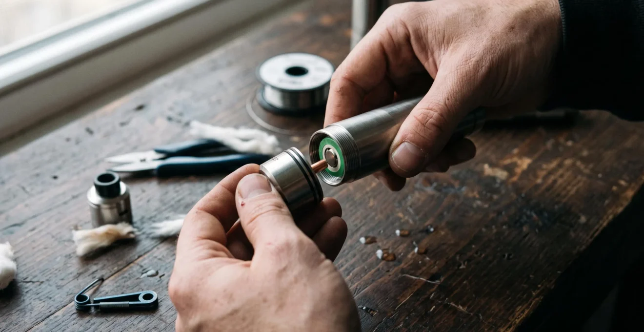
A direct electrical connection changes a mechanical vape because the battery supplies the atomiser without an electronic circuit actively controlling output. Coil power therefore depends on the cell’s available voltage, the electrical resistance of the circuit and losses through its physical contacts. As the battery discharges, the heating behaviour changes rather than remaining at a selected wattage.
This distinction affects more than vapour production. A mechanical mod typically lacks the electronic safeguards found in regulated devices, including automated low-voltage cut-off, short-circuit detection and current limiting. Battery selection, atomiser compatibility and contact condition consequently have a more direct influence on electrical safety.
Direct battery connections also require a distinction between conventional mechanical designs using an insulated 510 connector and hybrid arrangements in which the atomiser’s positive pin contacts the battery itself. Both operate without electronic power regulation, but their contact geometry introduces different risks.
Understanding these differences requires examining battery discharge, resistance, contact integrity and the limits of the components involved.
Direct electrical connections: essential points
- Output follows battery voltage: mechanical mods do not electronically compensate for declining cell voltage, so coil power generally decreases during discharge.
- Electrical contact quality matters: contamination, deformation and incompatible hybrid connections can change circuit behaviour or create dangerous faults.
- Protection depends heavily on correct hardware assessment: a direct-output device cannot be relied upon to interrupt excessive current, reverse-polarity faults or over-discharge automatically.
- Why Does a Direct Battery Connection Change Output as the Cell Discharges?
- How Can You Inspect Direct Vape Contacts for Dirt, Wear or Poor Connection?
- Direct Connection or Regulated Output: How Do the Two Vape Designs Differ?
- Why Can a Direct Electrical Vape Connection Leave Less Margin for User Error?
- When Should Mechanical Vape Contacts Be Cleaned or Replaced?
- Consistent Wattage or Direct Output: Which Changes Less as Battery Charge Falls?
- Why Are Voltage, Current and Resistance Linked in a Vape Circuit?
- How Does Electrical Resistance Affect Power and Heating in a Vape Coil?
Why Does a Direct Battery Connection Change Output as the Cell Discharges?
A direct battery connection changes output during discharge because there is no electronic converter maintaining a fixed voltage or wattage at the atomiser. As the lithium-ion cell’s available terminal voltage decreases, current through an approximately constant-resistance coil also decreases. The result is progressively lower electrical heating power, although the decline is not uniform throughout the discharge cycle.
The underlying relationship is P = V²/R, where P represents power in watts, V is the voltage across the coil and R is its resistance in ohms. Because voltage is squared, even a moderate voltage reduction can produce a noticeable change in power when resistance stays approximately constant.
Hypothetical example: one coil at two voltages
Consider an ideal circuit containing a fixed 0.5-ohm resistor. At 4.2 V, its calculated power is 35.28 W, with a current of 8.4 A. At 3.3 V, the same resistance dissipates 21.78 W and draws 6.6 A.
This represents a calculated power reduction of approximately 38%. It is a mathematical illustration, not a measured vaping-device result or a recommended operating configuration. Actual coil voltage may be lower because of battery internal resistance and contact losses, while coil resistance may change as it heats.
The calculation follows the OpenStax physics equations for electrical circuits, which establish the relationships among voltage, resistance, current and dissipated power.
Battery discharge is not a straight-line process. According to Battery University‘s explanation of battery discharge, cell voltage may remain comparatively stable through much of the usable discharge period before declining more sharply near depletion. The actual curve depends on cell chemistry, current draw, temperature and operating conditions.
As available power changes, coil heating and aerosol generation may also change. Differences in flavour perception or vapour quantity are possible, but they cannot be quantified from electrical equations alone because airflow, liquid composition and coil construction also matter.
Of particular importance, a mechanical mod has no inherent electronic low-voltage cut-off. A weakening output signal is not a dependable measure of remaining charge. Discharge must be managed according to the battery manufacturer’s specifications, using appropriate external measurement rather than a generic voltage threshold.
Battery voltage establishes the starting electrical conditions, but the physical contacts determine how much of that voltage actually reaches the atomiser.
How Can You Inspect Direct Vape Contacts for Dirt, Wear or Poor Connection?
Direct vape contacts should be inspected with the battery removed and the device fully inactive. Examine the atomiser’s positive pin, the connector surfaces, relevant insulating components and mechanical switching contacts for contamination, wear, deformation or heat damage. A hybrid connection requires particular caution because its atomiser pin can contact the battery terminal directly.
Begin by separating the device components according to the manufacturer’s instructions. Inspect them in good lighting without inserting a battery or testing an assembled circuit. Contact surfaces should be clean, mechanically stable and free from visible electrical damage.
A practical visual assessment follows this order:
- Inspect the atomiser connection. Look for liquid residue, dirt, corrosion, pitting or damaged metal surfaces around the positive centre pin.
- Check the connector assembly. Identify whether the device uses a conventional insulated 510 connection or a direct-battery hybrid arrangement.
- Examine the insulators. Look for cracks, displacement, melting or deformation that might compromise electrical separation.
- Check moving contacts. Observe signs of mechanical wear, weakened springs, sticking components or damaged contact faces.
- Inspect the removable cell separately. Check the wrapper, terminal insulator and visible terminal surfaces for damage or contamination.
These checks do not establish electrical safety by themselves. Some faults, including internal shorts or unstable contact resistance, may remain invisible.
Contact resistance is electrically significant because metal interfaces are not perfect conductors. A contaminated or damaged connection introduces additional resistance into the circuit. This may reduce the voltage reaching the coil while generating unwanted heat at the affected contact.
A conventional 510 connector incorporates an insulated positive contact within the device’s connector assembly. A hybrid connection removes that intermediate positive contact and places the atomiser’s centre pin against the cell terminal. As explained in Vaping360‘s comparison of mechanical and regulated mods, not every atomiser with a standard 510 thread is suitable for this configuration.
A recessed, flush or spring-loaded atomiser pin can create a dangerous short-circuit condition in an incompatible hybrid arrangement. Visible protrusion alone should never be treated as proof of compatibility; the specific manufacturer’s requirements take precedence.
Unusual contact heating, intermittent activation, visible arcing or burn marks require immediate withdrawal from use. Attempting repeated activation to diagnose such a fault can increase the hazard.
Five checks to document before evaluating a mechanical connection
- Identify the connector architecture. Record whether the manufacturer specifies a standard 510 or direct-battery hybrid interface.
- Inspect the atomiser pin. Record any contamination, damage, movement or uncertainty about the manufacturer’s compatibility requirements.
- Examine contact surfaces and insulators. Create a written defect list identifying corrosion, deformation, cracks or heat marks.
- Assess battery condition. Record the cell model and any visible wrapper, terminal or insulating-ring damage.
- Establish a disposition. Mark the assembly as requiring manufacturer confirmation, professional assessment, replacement or no further action based on documented evidence; never treat an incomplete inspection as a pass.
Contact integrity is only one part of the distinction between mechanical and regulated hardware. The circuit architecture determines which electrical conditions a device can actively monitor or control.
Direct Connection or Regulated Output: How Do the Two Vape Designs Differ?
A mechanical vape connects the battery to the atomiser through a largely passive electrical path, whereas a regulated device places electronic control circuitry between the power source and heating element. The regulator can adjust output and implement electrical protections. The mechanical arrangement depends on battery voltage, coil resistance and contact condition without actively stabilising delivered power.
In a mechanical device, activating the switch completes the electrical circuit. Current then flows according to the available voltage and total circuit resistance. No regulation chip automatically maintains a chosen output setting as battery conditions change.
Regulated devices typically use electronic switching and control systems to monitor electrical conditions and adjust power delivery. Their specific capabilities depend on the model, firmware and manufacturer.
The main differences can be summarised as follows:
| Characteristic | Mechanical direct output | Regulated output |
|---|---|---|
| Power delivery | Determined by cell voltage and circuit resistance | Electronically controlled within operating limits |
| Output consistency | Generally changes as the cell discharges | Can maintain selected wattage while operating conditions permit |
| Low-voltage cut-off | No inherent electronic protection | Commonly incorporated |
| Short-circuit protection | No inherent automatic electronic interruption | Commonly incorporated |
| Current limiting | Not electronically enforced | May be enforced by device circuitry |
| Temperature control | No electronic temperature regulation | Available on compatible models |
| Reverse-polarity protection | No inherent electronic safeguard | Model-dependent |
| Failure considerations | Contact, switch, battery and compatibility faults | Battery and connector faults plus electronic-system limitations |
Electronic regulation improves control over output but does not eliminate every electrical hazard. A regulated product can still fail, and the presence of a chip does not demonstrate that every possible battery or atomiser fault is safely managed.
Likewise, a mechanical mod is not necessarily more powerful. Its apparent simplicity removes a layer of electronic control, but maximum output remains constrained by the battery, coil and physical circuit. A suitably designed regulated system may deliver comparable or greater power.
Mechanical simplicity should not be confused with electrical protection. Removing electronic components can eliminate certain electronic failure modes while also removing automated safeguards.
Claims that a direct connection always responds faster are also too broad. Real activation behaviour depends on switching electronics, contact characteristics, coil thermal mass and the particular devices being compared. The supplied technical evidence does not establish a universal response-time advantage.
These differences explain why mistakes involving cell suitability, resistance or connector compatibility have especially serious implications in an unregulated circuit.
Why Can a Direct Electrical Vape Connection Leave Less Margin for User Error?
A direct electrical connection leaves less margin for user error because the device generally cannot detect or electronically interrupt dangerous operating conditions. Excessive current demand, an incompatible atomiser connection or a damaged battery may therefore create a hazardous circuit without an automatic protective response. Correct component selection and independent verification become essential rather than supplementary.
Consider an atomiser with unexpectedly low resistance. At a given battery voltage, lower circuit resistance increases current demand under Ohm’s law. If the requested current exceeds the cell’s permissible operating conditions, the absence of electronic current limiting becomes a major concern.
Battery capability must be evaluated from the exact cell manufacturer’s documentation, particularly the applicable continuous-discharge rating and associated conditions. A marketing label alone does not establish safe operating current.
Hybrid connections introduce a separate risk. The atomiser’s positive centre pin must maintain the electrical separation required by the manufacturer’s design. An incompatible or unstable pin can allow unintended conductive paths, potentially producing a short circuit.
A damaged cell wrapper or terminal insulator also matters. In metal-tube devices, unintended contact between exposed cell surfaces and conductive housing components may bypass the intended electrical path.
The FDA presentation on electrical safety in vaping products identifies high current draw, interchangeable battery cells and limited protective controls among relevant safety concerns. Its historical discussion includes battery-related incidents reported during 2009–2017; it does not establish current incident rates or a quantified comparison between mechanical and regulated devices.
Several considerations therefore require separate verification:
- Cell authenticity and condition: the exact battery model, its documented limits and the physical integrity of its insulating components.
- Electrical load: independently verified resistance and a calculated current demand that can be assessed against manufacturer specifications.
- Connector compatibility: explicit confirmation that the atomiser and device are designed to operate together.
- Device integrity: undamaged insulation, stable contacts and a properly functioning mechanical switch.
None of these checks guarantees the absence of latent electrical defects. If the battery specifications, connector design or atomiser resistance cannot be verified, the safe decision is not to energise the assembly.
Sharing or borrowing mechanical equipment also introduces uncertainty. Another person’s device may contain a different cell, modified atomiser or previously damaged component that is not obvious during a casual inspection.
Because physical condition contributes directly to both circuit resistance and short-circuit risk, maintenance decisions must distinguish removable contamination from irreversible mechanical damage.
When Should Mechanical Vape Contacts Be Cleaned or Replaced?
Mechanical vape contacts should be assessed when performance changes unexpectedly, activation becomes irregular, liquid reaches the connector or visible contamination appears. Cleaning may be appropriate for removable surface residue when the manufacturer permits it. Replacement or professional evaluation is necessary when contacts, springs, insulators or other conductive components show damage that cleaning cannot correct.
A fixed maintenance interval cannot account for differences in connector construction, liquid exposure, switching frequency and environmental conditions. Observable changes are therefore more useful triggers for inspection than an unsupported universal schedule.
E-liquid leakage can leave deposits on the atomiser and connector surfaces. Condensed liquid, sweetener residue and environmental dirt may form films that interfere with electrical contact. Where these deposits increase contact resistance, they may contribute to voltage loss or localised heating.
However, unexpected heat at a contact is a fault warning, not simply a cleaning reminder. The device should be removed from service rather than repeatedly activated to see whether the problem disappears.
Routine care should follow the manufacturer’s maintenance instructions. With the battery removed, an approved soft, non-abrasive cleaning material may be suitable for accessible contact surfaces. Cleaning liquids, if permitted, must be used only as specified, and components must be completely dry before any further evaluation. Abrasive tools, aggressive scraping or improvised chemical treatments can damage protective finishes or alter critical contact geometry.
Replacement is more appropriate when inspection identifies:
- Pitting, burning or permanent deformation of a conductive contact.
- A spring that is compressed, fractured or unable to return reliably.
- Cracked, displaced or heat-damaged insulation.
- Unstable mechanical contact or damaged connector components.
- Persistent irregular operation despite manufacturer-approved maintenance.
A compromised contact should not be reshaped or polished into apparent compatibility without explicit manufacturer guidance. This is especially important in hybrid connections, where the atomiser pin and battery terminal form a direct interface.
Battery wrappers and insulating rings require their own assessment. A compromised cell should be kept out of service and handled according to the cell manufacturer’s safety instructions, rather than being treated as an ordinary dirty contact.
Once contact integrity is established, the remaining question is how effectively each device architecture maintains predictable output as the available battery voltage decreases.
Consistent Wattage or Direct Output: Which Changes Less as Battery Charge Falls?
A regulated device operating in constant-wattage mode generally changes less as battery charge falls. Its electronics compensate for declining cell voltage to maintain the selected output within the device’s supported operating range. A mechanical device provides no equivalent compensation, so power delivered to an approximately constant-resistance coil declines as the battery’s available voltage falls.
This distinction affects repeatability. In a regulated device, the user can select a wattage that the electronics attempt to reproduce during subsequent activations. As the battery becomes depleted, the device eventually reaches its operating limits and may reduce output or stop firing.
The transition is not necessarily a gradual reduction in wattage. Some regulated systems maintain the requested power and then interrupt operation at a defined protection threshold. Others may limit output earlier because of current, voltage, temperature or other system constraints.
A direct-output device behaves differently. It does not establish a fixed power target; instead, the coil receives the electrical conditions made available by the battery and the rest of the circuit at that moment.
These two behaviours offer different forms of control:
| Evaluation factor | Constant-wattage regulation | Mechanical direct output |
|---|---|---|
| Power target | Selected electronically | No electronically selected target |
| Response to declining voltage | Compensation within operating limits | Power generally declines |
| Repeatability | Greater while regulation remains effective | Dependent on changing electrical conditions |
| End-of-discharge behaviour | Typically power limiting or protective shutdown | No inherent low-voltage shutdown |
| Primary design trade-off | Electronic control and additional system complexity | Mechanical simplicity with reduced automatic protection |
Regulation introduces electronic circuitry and its associated switching and control behaviour. However, the presence of such electronics does not establish a perceptible activation delay. No supported measurement demonstrates that otherwise comparable mechanical devices always respond faster.
The same atomiser may also behave differently between the two architectures. A regulated device set to a particular wattage does not necessarily reproduce the varying power profile of a direct-output device. Likewise, an atomiser arrangement assessed for one circuit cannot be assumed suitable for another, particularly where battery-current limits or hybrid connector requirements differ.
For users prioritising repeatable electrical conditions and adjustable output, regulation offers the clearer technical advantage. Mechanical hardware instead exposes the load more directly to the battery’s changing state and places greater responsibility on component compatibility.
To understand how these profiles arise—and why current demand cannot be separated from safety—the governing voltage, resistance and power relationships need to be considered together.
Why Are Voltage, Current and Resistance Linked in a Vape Circuit?
Voltage, current and resistance are linked because the electrical potential across a conductive load determines the current through it according to its resistance. Ohm’s law expresses this as I = V/R. In a vape circuit, that current contributes to the electrical power dissipated by the heating coil, making these quantities inseparable when evaluating battery demand and heating behaviour.
For a simplified resistive circuit, three equations describe the relationship:
- Current: I = V/R, expressed in amperes.
- Electrical power: P = VI, expressed in watts.
- Power at fixed resistance: P = V²/R.
These equations explain why decreasing coil resistance at a fixed applied voltage increases both current and dissipated power. A lower resistance does not merely change the intensity of heating: it also increases the electrical demand placed on the battery.
The difference matters because removable lithium-ion cells have manufacturer-defined operating limits. Their continuous-discharge capability cannot be derived solely from nominal capacity, physical size or the resistance of a coil.
For a hypothetical ideal circuit, a 0.5-ohm resistance at 4.2 V draws 8.4 A. This mathematical result does not establish that a particular cell can safely sustain that load. Battery specifications, operating conditions and potential fault currents must be evaluated independently.
Actual mechanical circuits are more complicated than a single ideal resistor. Battery internal resistance, connector resistance, switch contacts and conductor losses all influence the voltage present across the coil. Circuit resistance may also vary as components heat.
For this reason, the resistance of a manually assembled coil should not be accepted solely from a nominal design value or an unverified display. An appropriate calibrated resistance-measuring instrument can identify discrepancies that might materially affect calculated current demand.
Measurement must also be interpreted correctly. An ordinary handheld multimeter can have significant uncertainty when measuring very low resistance, particularly if probe lead resistance and contact quality are not accounted for. Equipment suitable for low-resistance measurements is therefore important.
A resistance measurement alone does not prove the absence of intermittent shorts, insulation faults or incompatible connector geometry. Likewise, a calculated steady-state current does not fully describe transient fault behaviour or guarantee that a battery will remain within its thermal limits.
Before evaluating any direct-output assembly, the relevant electrical data should therefore be treated as a set: verified coil resistance, battery-specific discharge specifications, connector compatibility and the condition of the entire current path.
Even when voltage and resistance are known, the coil’s thermal behaviour depends on factors beyond its electrical resistance alone.
Key takeaways before assessing coil heating
- Electrical power calculations describe energy delivery, but do not independently establish coil temperature or battery safety.
- The wire material, geometry and exposed heating surface influence how electrical energy is converted into heat.
- Changing battery voltage affects the coil’s heating conditions, while temperature-dependent resistance can further modify those conditions.
How Does Electrical Resistance Affect Power and Heating in a Vape Coil?
Electrical resistance influences vape-coil heating by controlling the current and power associated with an applied voltage. At a fixed voltage, lower resistance increases electrical power dissipation, assuming the circuit can supply the required current. However, resistance alone cannot establish heating speed, operating temperature or aerosol production because coil mass, material, geometry and cooling conditions also contribute.
Electrical energy delivered to the coil is converted substantially into heat through resistive dissipation. The relationship P = V²/R indicates how much electrical power a simplified resistive load receives when the applied voltage and resistance are known.
That power contributes to the coil’s thermal response, but heat must also be transferred to the surrounding air, wick and liquid. Consequently, two coils with the same measured resistance and supplied power may operate at different temperatures.
Several physical characteristics explain the difference.
- Wire material: different metals and alloys exhibit different electrical resistivity and temperature-dependent resistance behaviour.
- Coil mass: a heavier heating element generally requires more energy to produce a comparable temperature rise when other relevant properties are similar.
- Surface area: the extent and geometry of the heating surface affect heat transfer to the wick, liquid and airflow.
- Airflow and liquid supply: cooling and evaporation can substantially change the temperature reached at a given electrical input.
Kanthal, stainless steel and nickel illustrate why material identification matters. Their electrical and temperature-response characteristics differ, so equal nominal resistance does not imply equal thermal behaviour or identical device compatibility.
For some materials, resistance changes appreciably as temperature rises. Electronic temperature-control systems can use known resistance–temperature relationships with compatible coils to estimate heating conditions. A conventional mechanical circuit provides no equivalent active temperature regulation.
As a result, a direct-output coil experiences two interacting effects: battery voltage evolves during discharge, and the resistance of the heating element may change as it warms. The simple fixed-resistance power equation remains useful as a reference model, but actual operating conditions can deviate from it.
Lower battery voltage generally means less available heating power for a coil whose resistance remains approximately stable. The resulting thermal response is nevertheless influenced by liquid saturation, airflow and coil construction. A weaker battery state therefore cannot be translated into a precise temperature or vapour-output prediction without additional measurements.
Nor does faster heating automatically imply better or safer operation. Excessive heating can occur when liquid supply or cooling becomes inadequate, and electrical calculations alone cannot determine whether the coil is operating under suitable thermal conditions.
For hardware assessment, resistance should be treated as one measured electrical property within a broader system, not as a standalone indicator of performance or safe operation.
Before any mechanical device is energised, independently verify the manufacturer’s battery and atomiser requirements, confirm the integrity of the electrical contacts and obtain qualified technical assessment whenever compatibility or component condition remains uncertain. A regulated device with documented protections offers a more controlled alternative when these safeguards cannot be independently assured.
Does a direct battery connection eliminate voltage drop?
No. A direct battery connection eliminates electronic output regulation, not physical electrical losses. Internal cell resistance, mechanical contacts, the switch and conductors can all contribute to voltage drop. The voltage actually present across the heating coil can therefore be lower than the battery’s open-circuit voltage.
Does a hybrid 510 connection work with every atomiser?
No. In a hybrid design, the atomiser’s positive centre pin contacts the battery terminal directly. Atomisers with unsuitable, recessed, flush or movable positive pins can create short-circuit hazards. Compatibility must be explicitly established using the requirements of the specific device and atomiser manufacturers.
Can a mechanical vape detect when its battery is almost empty?
A conventional mechanical mod has no electronic battery-state monitoring or automatic low-voltage shutdown. Reduced heating performance may accompany discharge, but it is not a reliable battery-level indicator. Appropriate external assessment and compliance with the cell manufacturer’s discharge limits are necessary to avoid excessive discharge.
Can adding a low-resistance coil compensate for declining battery voltage?
Lowering resistance can increase current and power at a given voltage, but it also increases electrical demand on the cell. It does not regulate the output or compensate safely for changes in charge state. Modifying resistance without verifying battery-current capability and the complete circuit can introduce serious hazards.
Is a mechanical vape safer if all its metal contacts appear clean?
Clean contacts can reduce contamination-related electrical problems, but visual cleanliness does not establish overall safety. Battery condition, internal resistance, insulation, switching components, atomiser compatibility and current demand remain important. Hidden faults may exist even when accessible metal surfaces appear undamaged.