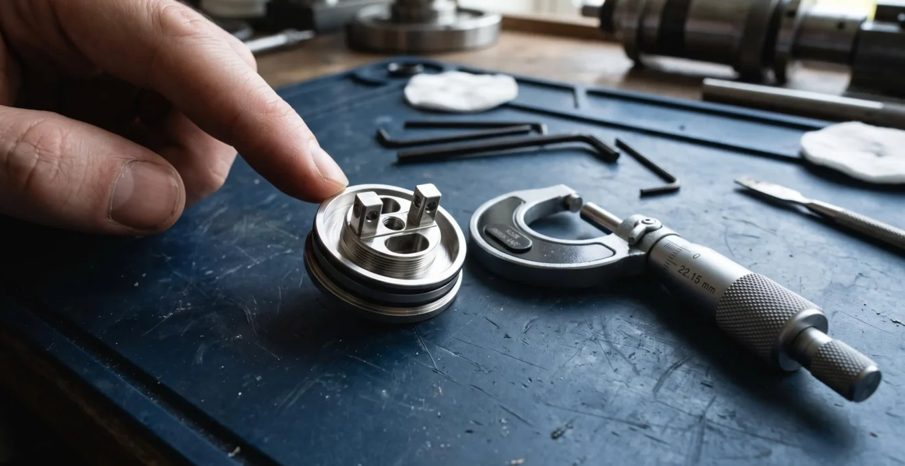
Machining precision determines how reliably a rebuildable vape atomiser’s individual components fit, seal and maintain their intended alignment. Small dimensional differences around the build deck, airflow passages, threads and O-ring grooves can alter assembly feel, leakage resistance and the space available for coil positioning. These effects may become apparent even when two atomisers have an almost identical external appearance.
Precision is not simply a matter of making every component fit as tightly as possible. A well-engineered atomiser needs controlled clearances, consistent sealing surfaces and sufficient allowance for temperature changes, material expansion and routine maintenance. Excessively restrictive fits can be as troublesome as poorly controlled ones.
For experienced rebuildable users, construction quality becomes easier to assess when each interface is examined according to its mechanical function. Thread engagement, seal compression, airflow alignment and electrical contact integrity reveal more than decorative finishing alone. Understanding these relationships also helps distinguish manufacturing problems from installation errors, worn components and unsuitable coil or wick arrangements.
Machining precision: the essential points
- Critical internal dimensions control component alignment, airflow geometry and the consistency of sealing interfaces.
- Good tolerances balance accurate engagement with enough clearance to accommodate residue, temperature changes and normal assembly.
- Thread resistance, repeated O-ring damage, connector instability and persistent leakage are reasons to inspect the hardware before further use.
- Why Can Tiny Machining Differences Change an Atomiser’s Draw and Leak Resistance?
- How Can You Inspect a Machined Atomiser for Thread and Seal Quality?
- Tight or Loose Machining Tolerances: Which Matter Most in an Atomiser?
- Which Machining Defects Can Cause Stuck Threads, Damaged O-Rings or Leaks?
- How Can You Maintain Precision-Machined Atomiser Threads Without Premature Wear?
- How Can Coil Position Improve Airflow Efficiency Inside a Rebuildable Atomiser?
- How Can You Check a Vape Device for Mechanical Wear Before Reassembly?
- Which Mechanical Limits Matter Most in High-Output Vape Hardware?
Why Can Tiny Machining Differences Change an Atomiser’s Draw and Leak Resistance?
Tiny machining differences can affect an atomiser’s draw and leak resistance by changing airflow clearances, component alignment and seal compression. A small deviation around an air inlet may change its effective opening, while an uneven sealing seat may prevent an O-ring from contacting its mating surface consistently. The result depends on the affected dimension and the atomiser’s design.
Airflow resistance depends on the geometry of the complete passage, including the inlet, internal channels, coil chamber and outlet. A slightly misaligned bore can change the effective flow area or create an additional obstruction. Where a flow passage is already narrow, a small dimensional deviation may represent a meaningful proportion of its intended clearance.
Deck depth and post spacing influence a different part of the system. They determine the available space for coil installation and can affect how consistently a coil can be positioned relative to the airflow openings and wick channels. These dimensions do not directly determine airflow resistance unless they alter the position of components in the flow path.
Sealing quality depends on the relationship between the O-ring, its groove and the opposing surface. A flat, appropriately finished mating face helps maintain even compression. Surface damage, uneven grooves or misalignment may leave local gaps through which liquid can migrate. Not every visible tool mark constitutes a leak path: its depth, direction and location relative to the seal matter.
A Parker Hannifin case study on sealing performance describes an aerospace enclosure whose failed leak tests prompted inspections of mating-surface finish and O-ring installation. Its redesigned sealing arrangement reduced potential leakage paths. Although the application was not an atomiser, it illustrates why surface geometry and seal installation must be considered together.
The distinction between functional and cosmetic precision is important. Two atomisers may share an attractive exterior finish while differing in airflow-channel alignment or seal-seat quality. Equally, visible machining marks on a non-contacting surface may have no functional consequence.
CNC manufacturing alone does not guarantee precision. The outcome depends on design specifications, tooling condition, inspection and process control. NIST research on precision mechanical assemblies discusses dimensional tolerancing and measurement strategies, although it does not establish atomiser-specific tolerances or performance thresholds.
Precision matters most where dimensions determine a mechanical function. Those critical interfaces are the logical starting point for inspecting a new atomiser rather than judging the quality of its exterior finish.
How Can You Inspect a Machined Atomiser for Thread and Seal Quality?
Inspect atomiser machining by examining clean threads, sealing faces and O-ring grooves before performing a gentle, liquid-free assembly test. Look for burrs, uneven wear, damaged seals, eccentric grooves and resistance during engagement. A component should assemble consistently without excessive force, although some normal resistance may come from correctly compressed seals.
Begin with the atomiser disconnected from its power source, completely cooled, cleaned and dried. Remove the coil and accessible O-rings where the manufacturer’s design permits. Use bright directional lighting and magnification to distinguish surface finishing from actual damage.
Check the external and internal threads for raised edges, flattened crests, debris or interrupted thread profiles. A lint-free swab can help reveal snagging points without exposing skin to sharp burrs. Avoid dragging a fingertip over a visibly damaged metal edge.
Next, inspect sealing faces and grooves. Regular concentric tool marks are not automatically defects, but grooves crossing a sealing contact area, nicks and uneven groove depths deserve attention. Examine O-rings separately for cuts, permanent flattening, swelling or loss of elasticity.
A dry-fit test is particularly useful because it separates mechanical engagement from problems caused by liquid, wicking or heat.
- Align the components carefully without applying downward force.
- Turn the threaded part gently in the loosening direction until the thread starts align, then engage it in the tightening direction.
- Complete the engagement using light finger pressure, stopping immediately if resistance becomes abnormal.
- Repeat a small number of times and note any consistent sticking point, wobble or gritty sensation.
A liquid-free airflow check can reveal an obvious bypass: with the unpowered atomiser assembled as designed, cover an appropriate air inlet and apply only a gentle draw. This is a qualitative observation, not a validated pressure or leak test. Some airflow systems intentionally include passages that make such checks inconclusive. A dry wick or paper placed near a seam cannot reliably prove that the system will remain leak-free when filled.
The first assemblies deserve particular care. Forcing rough or misaligned metal threads can create permanent scoring or galling. A slightly resistant joint should not be treated as an opportunity to wear the threads into shape.
Five checks to document before assembly
- Inspect both thread profiles under directional light and record any visible burr, dent or flattened crest.
- Examine each accessible sealing face and note the location of scratches crossing its contact area.
- Remove and inspect the O-rings, recording cuts, compression marks or unusual swelling.
- Perform a gentle dry-fit and note whether binding occurs consistently at the same engagement position.
- Check the assembled component for perceptible play and record whether it disappears when fully seated without force.
A smooth dry-fit does not prove perfect machining, but it provides a useful baseline. Understanding which interfaces actually require close control helps interpret the inspection results without treating every small clearance as a defect.
Tight or Loose Machining Tolerances: Which Matter Most in an Atomiser?
The most important machining tolerances are those controlling sealing geometry, thread compatibility, airflow alignment, insulation and electrical contact fit. Other features can accommodate greater clearance without affecting performance. The objective is not the smallest possible gap everywhere, but a dimensionally consistent assembly that remains functional through repeated use and temperature changes.
A tolerance defines the permitted variation in a manufactured dimension. Clearance describes the available space between mating components. A close-fitting part may be accurately manufactured, but a deliberately looser fit can also be precise when it matches the engineering specification.
The following comparison separates interfaces requiring particularly controlled geometry from those where some clearance is expected.
| Component or interface | Required dimensional control | Consequences of an unsuitable fit |
|---|---|---|
| Threaded connections | Compatible pitch, profile, alignment and suitable clearance | Binding, cross-threading, galling or wobble |
| O-ring grooves and sealing faces | Controlled groove geometry, surface condition and compression | Leaks, seal extrusion, cutting or excessive assembly force |
| Airflow bores and channels | Consistent effective opening and alignment | Unexpected airflow resistance or asymmetric flow distribution |
| 510 connector and insulator | Reliable contact geometry and electrical separation | Intermittent contact, unstable readings or short-circuit risk |
| Wick channels and clearance spaces | Design-dependent clearance suited to the intended wicking arrangement | Restricted liquid delivery or poor leakage control |
| Non-functional exterior surfaces | Finish and dimensional control appropriate to appearance and handling | Primarily cosmetic differences unless fit or structural integrity is affected |
Tolerance stacking explains why individually acceptable dimensions can still produce an unsatisfactory assembly. Imagine, hypothetically, a deck near the shallow end of its permitted depth combined with an insulator near the upper end of its height range. Their combined geometry could reduce available coil clearance or change the relationship between a contact and its surrounding parts.
Neither component would necessarily be defective in isolation. The issue would arise from the combined dimensional variation, particularly if the original design failed to allow enough assembly margin.
There is also a distinction between precision and excessively restrictive engagement. Threads with minimal clearance may initially feel exceptionally solid, yet become difficult to operate when residue accumulates or components expand differently with temperature. Conversely, loose threads may tolerate contamination while providing insufficient alignment or stability.
Thermal behaviour depends on the materials involved, their dimensions and the temperatures reached. Parts made from different metals or insulating polymers do not necessarily expand at the same rate. A joint that seats correctly when cold can therefore develop different contact pressure or clearance during heating.
No universal numerical tolerance can be assigned to rebuildable atomisers from general precision-engineering literature. Critical dimensions must be evaluated against the manufacturer’s actual design requirements.
Once the purpose of each fit is understood, visible defects become easier to classify. The next question is whether an observed imperfection is merely cosmetic or a likely source of mechanical failure.
Which Machining Defects Can Cause Stuck Threads, Damaged O-Rings or Leaks?
Burrs, damaged thread profiles, poor alignment, sharp sealing grooves and defective mating surfaces can cause sticking, premature O-ring wear or leakage. Each defect affects a particular interface: threads require compatible geometry, seals need suitable compression and surface contact, and airflow passages must maintain their intended boundaries. Observed symptoms help locate a fault but rarely identify its cause conclusively.
A burr is a raised edge of material left by machining or subsequent damage. On a thread, it can interfere with engagement and scratch the mating surface. Depending on the materials and contact conditions, sliding metal surfaces may also experience adhesive wear or galling, potentially making the connection progressively harder to separate.
Damaged or poorly formed thread entrances can make components difficult to start correctly. A missing or irregular lead-in chamfer may increase the likelihood of misalignment, although cross-threading can also result from incorrect handling.
O-ring damage has a different mechanical origin. A sharp groove edge can cut an elastomer during installation, while excessive compression can deform it. An unsuitable groove may allow the seal to move or pinch between adjacent parts. Repeated damage in the same location suggests examining groove geometry and the mating surface rather than repeatedly replacing the seal without investigation.
Leakage at a sealing interface may originate from a scratch, contaminated contact area, damaged O-ring or insufficient compression. Liquid emerging from an airflow opening, however, is not automatically evidence of a machining defect: excess liquid, condensation and unsuitable wicking can produce similar symptoms.
Several observations help narrow the diagnosis:
- Resistance at the same thread position: inspect for a local burr, dent or damaged thread section.
- Repeated seal cuts in one location: examine the corresponding groove edge and opposing surface.
- Persistent movement after full engagement: check for worn or mismatched mating components.
- Leakage at a consistent seam: assess the seal condition, groove cleanliness and seating geometry.
These patterns are diagnostic clues, not definitive proof of factory defects. Cross-threading, excessive tightening, abrasive cleaning and impact damage can reproduce many of the same symptoms. Randomly occurring resistance does not automatically indicate user error, just as a repeatable sticking point does not establish a manufacturing fault.
Material combinations also influence durability. For example, stainless-steel and aluminium components differ in hardness and wear behaviour. The risk of thread damage depends on surface treatment, contact pressure, lubrication conditions and the specific alloy pairing rather than the metal names alone.
The NASA Fastener Design Manual covers thread classes, material selection, lubrication, torque and fatigue in mechanical fasteners. It provides general engineering context, not atomiser-specific tightening values or approval for lubricants used in inhalation-related equipment.
A suspected defect should be assessed before additional tightening or modification. Once thread damage is established, routine cleaning may improve cleanliness but cannot restore the original machined geometry.
How Can You Maintain Precision-Machined Atomiser Threads Without Premature Wear?
Maintain precision-machined threads by preventing residue accumulation, aligning parts carefully and avoiding excessive tightening. Clean accessible thread roots with suitable non-abrasive tools, inspect the mating surfaces regularly and replace damaged components rather than forcing engagement. Lubrication requires particular caution because substances applied near an atomiser may migrate toward liquid or airflow passages.
Thread maintenance begins with identifying contamination before it becomes compacted between mating surfaces. Liquid residue, dust, detached fibres and metallic particles can increase friction or interfere with smooth engagement. Repeated assembly under contaminated conditions may scratch protective finishes or accelerate wear.
After removing the atomiser from its power source and allowing it to cool, separate the components according to the manufacturer’s instructions. Use a clean, soft brush or lint-free swab to remove deposits from accessible thread roots. Avoid abrasive compounds, metal scrapers and aggressive polishing, which can change surface geometry or remove protective coatings.
Periodic deeper cleaning may be necessary when residue remains after brushing. Cleaning agents must be compatible with the specific metals, coatings, polymers and seals. Removable parts should be cleaned only as permitted by the manufacturer, and all components must be completely clean and dry before reassembly. Electrical assemblies and non-removable contacts should not be immersed unless expressly designed for that treatment.
Routine lubrication is not automatically appropriate. Although mechanical-fastener engineering considers lubrication a way to alter friction, that principle does not establish the safety of applying oils, greases or anti-seize compounds inside vaping hardware.
Use only a material explicitly approved by the atomiser manufacturer for the precise application and location. Without such guidance, avoid adding lubricants to threads, sealing surfaces and adjacent airflow or liquid-contact areas. General-purpose industrial lubricants should not be assumed suitable for inhalation-related equipment.
Good engagement habits are equally important. Align the parts without lateral pressure, locate the thread start gently and tighten only enough to achieve the manufacturer’s intended seating. Counting turns can help detect an unusually early stop on a familiar assembly, but rotation count alone cannot confirm correct engagement.
During maintenance, compare present behaviour with the component’s earlier condition. Smooth thread flanks that have developed a slight polished appearance may reflect ordinary use. Increasing play, damaged crests, persistent binding or repeated seal deformation point toward potentially significant wear.
Machined interfaces have a finite service life. Cleaning can remove contamination but cannot replace lost material, recreate a damaged thread profile or correct a permanently distorted sealing seat.
Once an atomiser’s mechanical interfaces remain stable, coil positioning becomes a separate consideration. The accuracy of its deck and airflow geometry determines how consistently a rebuildable setup can be aligned.
How Can Coil Position Improve Airflow Efficiency Inside a Rebuildable Atomiser?
Coil position influences how air passes around and through the heated coil region, affecting local flow distribution, cooling and aerosol transport. Aligning the coil with the intended airflow openings can reduce unnecessary obstruction and improve consistency between builds. The best position depends on chamber geometry, wick placement and the manufacturer’s design rather than a universal height or distance.
Airflow entering an atomiser encounters changes in direction and cross-sectional area as it approaches the coil. A coil placed directly in the intended flow path receives a different distribution of moving air from one located significantly above, below or to the side of that path.
Misalignment may create uneven flow around the coil, local recirculation or additional resistance. These effects are geometry-dependent. A perfectly symmetrical arrangement is not necessarily optimal in an atomiser designed with intentionally offset or angled airflow openings.
Machining quality establishes the fixed geometry within which the coil must be positioned. Post height and spacing affect mounting flexibility, deck depth determines available vertical clearance, and airflow-bore alignment determines the location of incoming air relative to the build.
Two examples of the same atomiser design could therefore offer different usable adjustment ranges if their internal components depart from their intended dimensions. This is a mechanical possibility, not evidence that a specific model exhibits measurable inconsistency.
A practical alignment check begins with the device unpowered and the deck exposed. Compare the mounted coil’s position with the visible airflow openings from several angles. Check that the coil and its leads cannot contact the chamber wall, cap or other unintended conductive surfaces. Verify the manufacturer’s recommended clearances before proceeding.
If the manufacturer permits dry-firing, coil heating must be performed only with appropriate equipment, electrical checks and precautions for hot metal. An evenly glowing coil can help reveal electrical heating irregularities, but glow symmetry does not demonstrate symmetrical airflow. Air distribution cannot be established by looking at an energised coil alone.
Wick positioning introduces another constraint. Excessively compressed wick material can restrict liquid transport, while an insufficiently filled channel may allow unwanted liquid movement. Coil location relative to the wick ports affects the path and bend of the wick, potentially influencing saturation consistency.
A coil positioned too close to a conductive airflow structure also introduces a clearance concern. Dry hits or local overheating, however, cannot reliably be attributed to airflow proximity alone; power, liquid supply, wick condition and coil geometry all contribute.
The goal is a repeatable arrangement that respects three interacting requirements: the intended airflow path, adequate wick supply and safe mechanical clearance.
Even a correctly aligned build depends on stable hardware. Before reinstalling the atomiser, the condition of the connector, insulators and other mechanical interfaces deserves a separate inspection.
How Can You Check a Vape Device for Mechanical Wear Before Reassembly?
Before reassembly, inspect threads, O-rings, insulators, post screws and electrical contacts for wear or damage. Look for increasing clearance, corrosion, deformation, contamination and irregular contact surfaces. Mechanical condition should then be considered alongside appropriate electrical measurements, because a visually acceptable component can still have an unsafe or unstable electrical connection.
Begin with the atomiser removed from the mod, with the device powered off and its components cool. Where applicable, remove the battery according to the manufacturer’s instructions. Clean and dry the components so contamination does not conceal defects.
Threaded joints should engage smoothly without force. A small amount of polished contact wear may occur through normal use, but missing material, damaged crests, pronounced looseness or a progressively worsening fit suggest deterioration.
Next, examine the O-rings and insulating components. Seals should retain the shape and elasticity needed for their intended compression. Insulators should show no cracks, scorching, melting, displacement or unexplained dimensional changes. Do not attempt to repair a structurally damaged insulator with an improvised substitute.
Inspect post screws and their receiving threads for stripped profiles, rounded heads and poor engagement. Examine accessible contact surfaces for oxidation, pitting, contamination or evidence of heat damage.
The 510 connection requires particular attention because it combines mechanical engagement with electrical contact. Check that the connector’s insulating material is intact and that the contact geometry has not been altered by wear or impact. A recessed or unusually mobile contact may require manufacturer assessment rather than adjustment.
A flat-surface check can help identify obvious instability in a detached atomiser base. This observation is only meaningful when the base is designed to sit flat, and it does not establish dimensional accuracy.
Electrical checks must use appropriate measuring equipment. A suitable atomiser resistance meter can help identify unexpected resistance or short-circuit indications in an installed build. Its reading is not a comprehensive inspection of every electrical contact, and continuity testing of an isolated connector requires knowledge of the actual circuit configuration.
Never perform resistance or continuity measurements on an energised device. Unstable readings, unexpected continuity, visible insulation damage or evidence of contact overheating should be treated as reasons to stop use until the cause has been properly resolved.
Distinguishing normal wear from degradation depends on change over time. Minor polishing that remains stable is different from increasing wobble, recurring leakage, worsening contact behaviour or progressively higher electrical resistance under otherwise comparable conditions.
The FDA‘s advice on vape battery safety recommends following the manufacturer’s handling instructions and protecting devices from extreme temperatures. It does not provide a specific mechanical inspection standard for rebuildable atomisers.
Wear becomes especially important when equipment experiences repeated heating and cooling. Higher thermal loads can reduce the remaining margin of certain mechanical interfaces, making the final assessment one of operating limits rather than appearance alone.
Key takeaways before assessing high-output use
- A stable cold assembly does not automatically demonstrate adequate clearance or sealing performance at elevated temperatures.
- Insulator condition and electrical contact integrity take priority over cosmetic wear or a preference for tighter-fitting parts.
- Repeated heat exposure makes changes in thread engagement, seal elasticity and component alignment worth investigating promptly.
Which Mechanical Limits Matter Most in High-Output Vape Hardware?
High-output vape hardware is constrained by the temperature resistance of its insulators and seals, the stability of electrical contacts, the behaviour of threaded interfaces under heat and the strength of its structural components. Electrical capability alone does not establish mechanical suitability. Higher operating loads must remain within the complete device’s manufacturer-defined limits.
Heating produces dimensional changes in metal components and can alter the properties of nearby polymers and elastomers. The significance depends on the temperature reached, exposure duration, materials and interface geometry. A fit that works at room temperature may behave differently when the atomiser becomes hot.
Sealing interfaces illustrate this interaction. An O-ring must have appropriate compression and remain compatible with its operating environment. If the material hardens, swells, loses elasticity or takes a permanent compression set, leakage resistance may deteriorate even when the metal groove remains dimensionally unchanged.
Insulators are a more critical concern because their function includes maintaining electrical separation. Visible deformation, cracking, discoloration associated with overheating or displacement may indicate that the assembly can no longer maintain its intended insulating geometry.
Threaded connections experience combined effects from temperature, assembly force, repeated movement and contamination. Differential expansion may change engagement pressure, while residue and surface damage can make the connection harder to operate. Repeated forced disassembly of a hot or binding joint can accelerate mechanical deterioration.
Electrical contacts introduce another limit. Contact pressure, surface condition and connection stability affect how reliably current passes through the interface. Mechanical relaxation, contamination or wear may increase resistance and contribute to unwanted local heating. The relationship is device-specific and cannot be evaluated from machining appearance alone.
Thin machined sections and heavily stressed fastening points must also retain sufficient mechanical integrity. No general thickness or power threshold can be inferred without the actual dimensions, material properties and design validation of the device.
For equipment subjected to repeated high thermal loads, the following hierarchy is useful:
- Electrical insulation failure: stop use if insulation is damaged, distorted or unable to maintain separation.
- Unstable contacts: investigate unexpected resistance changes, contact movement or signs of local overheating.
- Loss of sealing integrity: examine hardened O-rings, persistent leaks and changes in seating.
- Progressive thread damage: identify galling, increasing play or binding before further assembly.
- Structural deterioration: reject cracked, visibly distorted or otherwise compromised load-bearing components.
These are inspection priorities rather than a validated ranking of failure probabilities. A visible symptom may have several causes, and an apparently undamaged atomiser is not automatically suitable for higher power.
Repeated heating and cooling can contribute to cumulative deterioration, but the rate of wear cannot be predicted from output setting alone. Actual temperature, material selection, maintenance, duty cycle and design margins all matter. Two devices operated differently may therefore age at different rates without either following a universal service-life pattern.
Machining precision contributes to reliability by establishing the intended contact, clearance and sealing geometry. It cannot compensate for materials operated beyond their limits, damaged insulation or unsuitable electrical conditions.
For an atomiser showing recurring leaks, unstable readings, binding threads or heat-related deformation, the appropriate next action is to stop using the affected assembly and consult the manufacturer’s specifications or a qualified repair professional. Mechanical integrity should be confirmed before any return to service, rather than attempting to overcome a questionable fit by increasing tightening force or operating power.
Does a smoother-looking machined surface always provide a better seal?
No. Sealing performance depends on the specified surface finish, groove geometry, O-ring material and compression, as well as proper assembly. A visually polished surface may still be misaligned or dimensionally unsuitable. Conversely, controlled machining marks can be compatible with a functional sealing interface.
Can machining accuracy be judged without professional measuring instruments?
Visual inspection and gentle dry-fitting can identify obvious burrs, damage, binding and excessive movement. They cannot establish whether a component meets a specified dimensional tolerance. That requires suitable measuring equipment, reference dimensions and a defined measurement procedure.
Should a new atomiser feel completely free of resistance when assembled?
Not necessarily. Normal O-ring compression and the intended mechanical fit can produce some resistance. The important distinction is between predictable, smooth seating and abnormal grinding, abrupt binding or the need for excessive force. Assembly feel must be interpreted in the context of the manufacturer’s design.
Can replacing an O-ring solve a leak caused by inaccurate machining?
A replacement seal can correct leakage caused by a damaged, aged or incompatible O-ring. It cannot reliably correct a badly damaged sealing face, unsuitable groove geometry or major misalignment. Repeated leakage with the correct new seal warrants inspection of the underlying components.
Can a high-quality atomiser become mechanically unreliable despite accurate manufacturing?
Yes. Correct initial tolerances do not prevent eventual wear, contamination, impact damage or deterioration from repeated thermal exposure. The durability of a precision-machined assembly depends on suitable materials, operating conditions, maintenance and the continued integrity of critical interfaces.