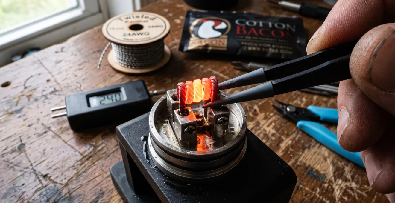
A metallic vape coil converts electrical energy into thermal energy through electrical resistance. When current passes through the heating wire, electrical power is dissipated as heat. That heat transfers to the surrounding e-liquid, allowing volatile components to evaporate and subsequently form the aerosol commonly called vapour.
The process sounds straightforward, but a device’s wattage setting does not tell the whole story. Coil material, wire dimensions, resistance, airflow and wick saturation all influence how quickly the coil heats, where its hottest regions develop and how consistently the liquid is vaporised.
Two coils operating at the same electrical power can therefore behave differently. One may respond quickly while another warms more gradually, and neither necessarily maintains a uniform temperature across every wrap.
Understanding these relationships helps explain temperature-control modes, uneven heating, dry hits and the different demands of single- and dual-coil configurations. The essential distinction is between the electrical energy supplied to the coil and the thermal conditions actually experienced by the liquid and wick.
Vape coil heating: the essentials
- Electrical resistance converts supplied power into heat, but wattage alone does not determine coil temperature or vapour production.
- Wire composition, geometry, airflow and liquid saturation influence heating speed and temperature distribution.
- Consistent vaporisation depends on compatible materials, sound electrical connections and adequate liquid delivery—not simply increasing wattage.
- How Does Electrical Resistance Affect Power and Heating in a Vape Coil?
- Why Do Vape Coil Metals Produce Different Heating Responses at the Same Power?
- Kanthal, Stainless Steel or Nichrome: Which Coil Material Suits Your Setup?
- How Can You Spot Uneven Heating Across a Vape Coil Before Normal Use?
- Why Does Uneven Heat Distribution Create Hot Spots on a Vape Coil?
- Which Coil Defects Can Create Hot Spots and Premature Wick Damage?
- How Can Coil Positioning Improve Heat Consistency Without Raising Wattage?
- Why Does a Dual-Coil Build Behave Differently From a Single-Coil Build?
How Does Electrical Resistance Affect Power and Heating in a Vape Coil?
Electrical resistance determines the relationship between voltage, current and power in a vape coil. When current flows through the resistance wire, electrical energy becomes heat through resistive dissipation. Lower resistance requires more current at the same delivered power, but neither resistance nor wattage independently determines how hot the coil becomes.
Ohm’s law describes the fundamental relationship between voltage (V), current (I) and resistance (R): V = I × R. Electrical power (P), measured in watts, is calculated as P = V × I. For an ohmic conductor, the equations can also be written as P = I² × R and P = V² / R.
These relationships describe electrical power dissipation, not the temperature of a particular coil wrap. Temperature also depends on how that energy is distributed and how quickly heat escapes into the liquid, airflow and surrounding atomizer structure.
Consider two explicitly hypothetical, ideal resistive loads supplied with a constant 4 V:
| Electrical quantity | 0.5 Ω load | 1.0 Ω load |
|---|---|---|
| Applied voltage | 4 V | 4 V |
| Resistance | 0.5 Ω | 1.0 Ω |
| Calculated current | 8 A | 4 A |
| Calculated power | 32 W | 16 W |
At constant voltage, halving resistance doubles current and power. At constant delivered power, however, a lower-resistance coil requires lower output voltage and higher output current. These conditions must not be confused.
A regulated mod may transform battery voltage before delivering power to the atomizer. Consequently, coil-side current is not necessarily battery-side current. Battery demand also depends on conversion efficiency, operating conditions and the device’s electronics. Poor electrical connections can introduce additional resistance and unwanted local heating, regardless of the displayed wattage.
For a practical electrical check, read the installed resistance on a suitable regulated device, record its wattage setting and confirm that the combination remains within the manufacturer’s supported operating limits. Voltage and current can then be calculated as ideal estimates. The screen’s selected wattage is a command or reported operating value, not independent proof of measured power at the coil.
The OpenStax explanation of electrical energy and power provides the underlying equations and explains how resistive loads convert electrical energy into heat.
Even where electrical power is accurately known, wire length, diameter, surface area and heat transfer determine the resulting temperature pattern. Concentrating the same power into a smaller heated surface can create different thermal conditions from spreading it over a larger one.
Once the electrical relationships are understood, the next question is why different resistance alloys respond differently even when the supplied wattage is nominally identical.
Why Do Vape Coil Metals Produce Different Heating Responses at the Same Power?
Different vape coil metals heat differently at the same power because their electrical resistivity, temperature-dependent resistance, heat capacity and thermal conductivity vary. Wire dimensions and construction further change the heating response. Equal wattage therefore does not guarantee equal ramp-up time, surface temperature, temperature distribution or aerosol output.
Electrical resistivity describes a material’s opposition to current independently of the wire’s particular dimensions. The resistance of a uniform wire depends on resistivity, length and cross-sectional area. Changing alloys while keeping a similar target resistance may require changing wire geometry, introducing further differences in thermal mass and surface area.
The temperature coefficient of resistance describes how a material’s electrical resistance changes with temperature. This matters because some regulated mods estimate coil temperature by comparing the resistance of a heated coil with its resistance at a reference temperature.
Stainless steel grades suitable for vaping can exhibit a sufficiently measurable resistance change to support compatible temperature-control systems. Kanthal is generally used in wattage mode because its relatively small resistance change makes it poorly suited to conventional resistance-based temperature estimation. Nichrome is likewise normally used in wattage mode.
Thermal response is a separate consideration. A coil’s heating speed depends on the rate at which electrical energy enters it, its effective heat capacity and the rate at which energy leaves it. A thin wire with relatively low thermal mass can respond differently from a large, complex wire assembly, even when both use the same alloy.
Experimental evidence: temperature varies across a coil
Researchers investigating Kanthal and nichrome coils used infrared temperature measurements under dry and liquid-saturated conditions, comparing contact and non-contact wire configurations.
During reported dry-heating experiments, temperatures near the central coil region were approximately 5–10% higher than at the ends. Liquid saturation substantially changed the measured temperatures, while wire configuration and liquid medium influenced the results. These measurements do not establish a universal performance ranking between the alloys.
The experimental study of Kanthal and nichrome coil temperatures demonstrates why material comparisons must account for coil construction and operating conditions rather than wattage alone.
For someone prioritising straightforward wattage operation, an appropriate Kanthal or nichrome coil may be suitable. Someone requiring compatible resistance-based temperature control will need an alloy supported by that mode, such as a specified stainless steel grade. Neither choice guarantees superior flavour, longevity or thermal uniformity.
Material properties become useful in practice only when combined with the device’s control mode, supported resistance range and the physical construction of the coil.
Kanthal, Stainless Steel or Nichrome: Which Coil Material Suits Your Setup?
Kanthal generally suits straightforward wattage-based builds, stainless steel offers compatibility with both wattage and certain temperature-control modes, and nichrome is another established wattage-mode option. The appropriate choice depends on mod compatibility, wire geometry, handling preferences and the desired heating response rather than an objectively superior metal.
For a rebuildable atomizer operated in fixed wattage mode, Kanthal is a practical candidate because it is commonly available as resistance wire and does not require temperature-control calibration. Its relatively stable resistance with temperature simplifies conventional power-based operation, although it provides little temperature information to the device.
Stainless steel is useful where the mod supports the specific grade and corresponding temperature-control profile. In wattage mode it works as a resistive heating element; in compatible temperature-control mode, its changing resistance provides feedback for estimating temperature.
Nichrome is often considered when selecting wire for a responsive wattage build. Yet apparent responsiveness cannot be attributed to alloy identity alone. A smaller or lighter nichrome coil may ramp up quickly, while a heavier construction can respond more slowly.
The following comparison focuses on realistic operating scenarios instead of promising a universal flavour or temperature ranking.
| Requirement | Material to consider | Important limitation |
|---|---|---|
| Simple regulated wattage operation | Kanthal | Not generally suitable for standard resistance-based temperature control |
| Wattage and compatible temperature-control operation | Stainless steel | Requires the correct grade and supported control profile |
| Responsive wattage-oriented wire configurations | Nichrome | Ramp-up depends strongly on wire dimensions and thermal mass |
| Rebuilding and maintenance | Any compatible alloy | Mechanical handling, wear and coil geometry remain important |
Handling differences also matter. Kanthal wire may require more force to shape depending on gauge and construction, while some nichrome wires feel easier to form but retain or recover their shape differently. Stainless steel’s mechanical behaviour varies by grade and wire processing. These are practical tendencies, not guaranteed properties of every commercially available wire.
After repeated heating, inspect for deformation, damaged wraps, persistent deposits or compromised connections. Excessive dry heating should not be treated as harmless maintenance. A deformed or degraded coil may warrant replacement rather than repeated attempts to restore its original appearance.
Perceived flavour also depends on airflow, liquid delivery, deposits and aerosol temperature. No evidence in the supplied research establishes one of these three alloys as universally delivering better flavour or longer service life.
Verify material compatibility before installation. Temperature-control modes require the appropriate wire and device settings. Pure nickel and titanium heating wires, for example, should not be assumed suitable for ordinary wattage operation simply because they can function in supported temperature-control systems.
Even a compatible metal cannot compensate for uneven installation or unstable electrical contacts. Those issues can create local overheating before the device displays an obvious error.
How Can You Spot Uneven Heating Across a Vape Coil Before Normal Use?
Uneven heating can be identified by inspecting coil geometry and electrical connections before use, then checking for abnormal resistance readings or signs of localised overheating. Unequal wrap spacing, loose terminals and damaged wire deserve attention. Glowing coils can reveal temperature differences, but repeated dry firing is not a risk-free diagnostic procedure.
Begin with the atomizer disconnected from power. Inspect the coil’s position, leg security, wrap spacing and clearance from surrounding metal components. Look for an accidental contact between the heating element and the deck or chamber, particularly where a wire leg approaches a post or housing.
Resistance measurement offers another diagnostic signal. A reading inconsistent with the expected build, an unexpected short-circuit warning or a value that changes substantially when the assembly is moved can indicate a connection or installation problem. Such symptoms justify stopping rather than compensating with additional wattage.
For a prebuilt or replaceable coil, follow the manufacturer’s installation instructions instead of attempting to reshape an internal heating element. For rebuildable coils, mechanical inspection and resistance verification should precede liquid saturation and normal use.
On certain rebuildable configurations, experienced users may perform brief, low-power diagnostic pulses in accordance with the relevant equipment guidance. An isolated wrap glowing earlier or markedly brighter than adjacent wraps can indicate uneven heating. However, a centre-to-outer-edge glow pattern is not a universal pass-or-fail standard, and spaced coils may behave differently from contact coils.
A glowing coil must not be pinched or repositioned while electrically energised. Any mechanical adjustment should take place with power disconnected and the coil cooled sufficiently to prevent burns. Ceramic-tipped tools do not eliminate every electrical or thermal hazard. Repeatedly heating wire to visible incandescence is also not necessary for every coil type.
Once the coil is installed and saturated, indirect symptoms may include inconsistent aerosol delivery, persistent burnt taste, local wick discolouration or unexplained changes in resistance. None proves a hot spot independently. Inadequate liquid supply, deposits, airflow restrictions and electrical faults can produce overlapping symptoms.
Five checks before using a rebuilt coil
- Identify the wire. Confirm the alloy and grade against the device’s supported operating modes; the deliverable is a verified material-mode pairing.
- Inspect coil clearance. With power disconnected, check wraps and wire legs for unintended contact with the deck or chamber; the deliverable is a visibly unobstructed installation.
- Check terminal connections. Confirm the wire is securely retained without visible damage; the deliverable is a mechanically stable coil.
- Verify electrical resistance. Use an appropriate resistance-reading device and compare the reading with the expected design and supported operating range; the deliverable is a recorded, plausible resistance value.
- Check wick preparation. Confirm the wick is correctly placed and fully saturated according to the atomizer’s instructions; the deliverable is a visibly wetted wick with an unobstructed liquid path.
If resistance is unstable, a connection is damaged or local heating remains unexplained, do not continue normal operation. Finding the source of uneven heating is more useful than masking its symptoms.
Why Does Uneven Heat Distribution Create Hot Spots on a Vape Coil?
Uneven heat distribution creates hot spots when particular regions of a coil generate or retain more thermal energy than surrounding regions. Localised electrical resistance, unintended contacts, irregular wire geometry and differences in cooling can contribute. These areas may heat the wick or liquid disproportionately, even when the device’s overall power setting appears normal.
In a simple, uniform resistive wire, local power dissipation follows the current passing through each segment and that segment’s resistance. Electrical current does not automatically concentrate heat wherever it encounters the lowest resistance: in a series conductor, the same current passes through successive segments, and higher local resistance can dissipate more power.
Unintended contact between adjacent wraps can change the effective current path by electrically bypassing parts of the wire. A poor terminal contact can instead introduce additional contact resistance and concentrated heating near a leg or post. These are distinct electrical mechanisms, although both can disturb the intended temperature distribution.
Even with sound electrical connections, the middle of a coil may run hotter than its ends because heat escapes differently through the wire legs, posts, airflow and surrounding liquid. Coil mass, wrap spacing and the position of the wick all influence the balance.
Approximately 5–10%
Higher central temperatures than end temperatures were reported during specified dry-heating experiments on Kanthal and nichrome coils. This experimental observation is not a universal temperature difference for all vape coils.
Inhalation Toxicology research on contact and non-contact heating coils.
When one region becomes unusually hot, liquid near that location may vaporise or thermally degrade differently from liquid elsewhere on the coil. Repeated overheating can contribute to deposits and unwanted flavour changes. If local liquid delivery cannot replace what is vaporised, the adjacent cotton may begin to dry out.
A persistently dry region is particularly concerning because liquid normally removes heat from the coil through warming and evaporation. Without sufficient liquid, the local balance changes and temperatures can increase rapidly.
Not every hot spot is correctable by adjusting wrap spacing. A transient installation irregularity may be resolved by a suitable mechanical correction, but damaged wire, unstable terminals or persistent abnormal resistance can indicate a structural fault requiring replacement.
Likewise, a burnt taste does not establish that a specific wrap-to-wrap contact caused it. Wicking limitations, deposits and operating conditions must also be considered.
The consequences become clearer when examining how coil damage and liquid-delivery problems interact with the cotton wick over repeated heating cycles.
Which Coil Defects Can Create Hot Spots and Premature Wick Damage?
Coil defects that contribute to local overheating include damaged wire, poor terminal connections, unintended electrical contacts and irregular coil geometry. Excessively tight, uneven or poorly saturated wicking can independently cause local dryness. These problems may accelerate cotton degradation, producing persistent off-flavours or inconsistent aerosol delivery before the entire coil appears worn.
Installation defects and wear-related defects require different responses. An incorrectly positioned rebuildable coil may be corrected before use if the wire remains intact and electrical readings are stable. Surface damage, severely distorted wraps, deteriorated terminals or recurrent abnormal heating are stronger reasons to replace the affected component.
Common issues include:
- Accidental wire contact: an unintended electrical connection can change the effective resistance and current path.
- Loose or damaged terminals: poor contact can cause resistance fluctuations and unwanted heating near the connection.
- Uneven wire legs: asymmetrical geometry may alter heat loss through the posts and the effective heated region.
- Overpacked cotton: excessive compression can restrict liquid transport through the wick.
- Insufficient cotton contact: gaps between the wick and heating surface can leave sections inadequately supplied with liquid.
- Wire deterioration: mechanical damage, corrosion or persistent deposits can affect electrical and thermal behaviour.
The wick deserves particular attention because it acts as the liquid-delivery interface between the reservoir and the heating element. Full reservoir capacity does not guarantee that liquid reaches every part of the cotton at the required rate.
Inspect the wick for sharply localised darkening, visibly dry patches or fibres that appear brittle or thermally damaged. Such findings can support a diagnosis of inadequate liquid supply or overheating, but colour alone cannot establish its cause. Deposits and liquid ingredients may also discolour cotton during normal use.
Laboratory findings: dry hits and cotton degradation
A 2024 toxicology study compared e-cigarette aerosol generated under dry-hit and liquid-saturated conditions using a defined experimental formulation and puffing protocol.
Microscopy revealed thermal decomposition of cotton following dry-hit conditions. The dry-hit exposures also produced greater cytotoxicity in the study’s in vitro lung-cell system. These results support avoiding wick drying, but they do not quantify the resulting clinical risk in humans or identify coil geometry as the sole cause of dry hits.
The PubMed record of a 2024 study on dry hits and wick damage documents the experimental comparison and its principal findings.
Correct priming is important, but it cannot repair a defective electrical connection, restore damaged cotton fibres or resolve a coil that repeatedly overheats in the same location. Re-saturating a previously scorched wick may remove immediate dryness without reversing the damage already sustained.
If persistent burnt taste is accompanied by visibly deteriorated cotton or abnormal electrical behaviour, replace the affected consumable or rebuildable components as appropriate. Continuing to increase power would aggravate rather than resolve the underlying heat-transfer problem.
Once the electrical assembly and liquid delivery are sound, coil placement relative to airflow offers another way to improve consistency without demanding more energy.
How Can Coil Positioning Improve Heat Consistency Without Raising Wattage?
Coil positioning can improve heat consistency by aligning the heating surface with the intended airflow and ensuring that liquid reaches the wire evenly. Correct clearance from surrounding components, stable wire legs and balanced wick contact help limit local thermal differences. These changes can improve vaporisation without requiring an increase in electrical power.
Airflow removes heat from the coil and transports the aerosol towards the mouthpiece. If one section of a coil receives substantially more cooling than another, the surface temperature can become uneven even when electrical power is distributed as intended.
In an atomizer designed for central coil placement, centring the element relative to its airflow inlets may reduce unnecessary asymmetry. Other atomizers deliberately use offset coils, side airflow or bottom airflow, so a geometrically centred position is not automatically optimal.
The device’s intended airflow path should determine placement. A coil positioned too close to the chamber wall can also create unwanted contact risk or uneven local heating, while one placed too far from the effective airflow region may receive inadequate cooling.
Wire-leg geometry has a subtler effect. Both legs carry the same series current in a single uninterrupted coil, so equalising leg length does not itself equalise current flow. However, comparable leg lengths and sound connections can help make the geometry and heat transfer through the posts more predictable.
The wick must distribute liquid across the active heating region without restricting transport from the reservoir. Cotton that is tightly compressed in one section and loose in another may cool the wire unevenly through differences in liquid contact and evaporation.
Practical positioning checks therefore involve three separate relationships: coil-to-airflow alignment, coil-to-deck clearance and wick-to-wire contact. Each should be evaluated within the atomizer manufacturer’s specified installation arrangement.
A change in coil position can also influence perceived flavour and aerosol output. However, a more consistent response at the same wattage should not be interpreted as proof of reduced harmful emissions or a universally lower operating temperature.
Once a build functions consistently, lower wattage may provide sufficient vaporisation for a particular user preference. That possibility should be tested within the approved operating range rather than assumed to apply to every coil.
These considerations become more demanding when two separate heating coils share the same electrical supply, because their resistances and liquid-delivery conditions must be considered together.
Key takeaways before comparing single- and dual-coil builds
- Compare electrical resistance and current paths before comparing vapour output; a second coil changes the total electrical load.
- Greater heating surface requires sufficient liquid replenishment and airflow, not merely a higher power setting.
- Two physically similar coils can heat unequally when their resistances, contacts or cooling conditions differ.
Why Does a Dual-Coil Build Behave Differently From a Single-Coil Build?
A dual-coil build behaves differently because two heating elements usually operate as parallel electrical branches, changing the total resistance and the distribution of current. Two identical parallel coils have half the resistance of either coil alone. Their combined heating surface and thermal mass also change power requirements, liquid consumption and temperature response.
For two resistances connected in parallel, the electrical relationship is 1/Rtotal = 1/R1 + 1/R2. If both coils have the same resistance, the equivalent resistance is half that value.
As an explicitly hypothetical example, two separate 1.0 Ω coils connected in parallel produce a total resistance of 0.5 Ω. Under an ideal constant 4 V supply, each branch receives 4 V and dissipates 16 W, making 32 W in total.
A regulated device configured to deliver 32 W to this dual-coil assembly would ideally distribute approximately 16 W to each identical coil. By contrast, a single 1.0 Ω coil supplied with 32 W would dissipate the entire 32 W in that one heating element.
Therefore, comparing a single coil and a dual coil at the same total wattage does not mean that each heating element receives the same individual power.
Parallel branches also react to resistance differences. At a given applied voltage, the lower-resistance branch carries more current and dissipates more power. Two coils that look identical may therefore contribute unequally to total heating if their resistances or electrical connections differ.
Measuring each coil individually before completing a rebuild can reveal major discrepancies. Measurements should be made with appropriate equipment, without unintended parallel electrical paths, and with the components disconnected from power. Values should be compatible with the intended assembly and the device’s supported resistance limits.
A close resistance match is useful, but it does not guarantee identical temperatures. One coil may receive different airflow, have a different wick density or lose heat differently through its mounting points. The same electrical power can still produce different local thermal conditions.
A dual-coil assembly often offers a larger total heating surface than a comparable single-coil build. This can support increased aerosol generation under suitable conditions, but the result also depends on total delivered power, thermal mass, e-liquid supply and airflow. Doubling the number of coils does not automatically double vapour production.
Liquid delivery becomes particularly important because each wick must replenish evaporated liquid. If one branch dries faster or receives less airflow, its thermal response can diverge from the other even with closely matched electrical resistances.
Current demand must also be understood in context. At fixed output voltage, reducing equivalent resistance increases total output current and power. At fixed output wattage on a regulated mod, battery-side current depends on the converter and battery conditions rather than simply equalling the current through the parallel coils.
For unregulated devices, battery loading and electrical safety require particular caution. The combined resistance must not be evaluated independently of battery ratings, voltage conditions, connections and the limitations of the complete device. An unexpectedly low or unstable reading is a reason not to energise the assembly.
Ultimately, dual-coil performance is a system-level outcome. Electrical symmetry supports predictable power sharing, while airflow and wicking determine whether that energy can be used consistently without local drying.
Before using a rebuilt assembly, verify the completed resistance, supported operating mode, electrical connections and wick saturation. If those checks reveal instability or unexplained overheating, correct the fault or replace the affected components rather than increasing wattage.
Does a hotter vape coil always produce more vapour?
No. Aerosol production depends on available liquid, heat transfer, airflow and operating conditions. Higher coil temperature does not guarantee proportionally greater aerosol output. If liquid replenishment becomes insufficient, additional heating may instead cause dry-hit conditions and wick deterioration.
Why does a vape coil sometimes heat slowly even at high wattage?
A coil with substantial thermal mass can require more energy to increase its temperature. Wire construction, heat loss, liquid saturation and actual delivered power also affect ramp-up. High selected wattage does not establish that the device delivers that power continuously or that the coil will reach a particular temperature quickly.
Can temperature-control mode prevent every dry hit?
No. Compatible temperature-control systems estimate temperature from resistance changes, but their accuracy varies by device and conditions. Research published in PLOS ONE found substantial differences between configured and independently measured coil temperatures in some tested systems. Temperature control cannot replace appropriate liquid delivery and sound coil installation.
Does a coil’s glowing centre mean it has a defect?
Not necessarily. Experimental measurements have shown hotter central regions during dry heating even in deliberately constructed coils. However, isolated abnormal glow, unstable electrical resistance or damaged wire may indicate a fault. Visible glow alone cannot establish that a build is thermally uniform or safe for normal operation.
Can a vape coil be damaged even if its resistance reading looks normal?
Yes. Resistance readings measure the electrical behaviour of the assembly, not the condition of every wire surface or wick fibre. Deposits, local thermal damage, inadequate liquid contact or deteriorated cotton may exist without an obvious change in the measured resistance. Electrical checks should therefore be combined with visual inspection and adherence to the manufacturer’s maintenance guidance.