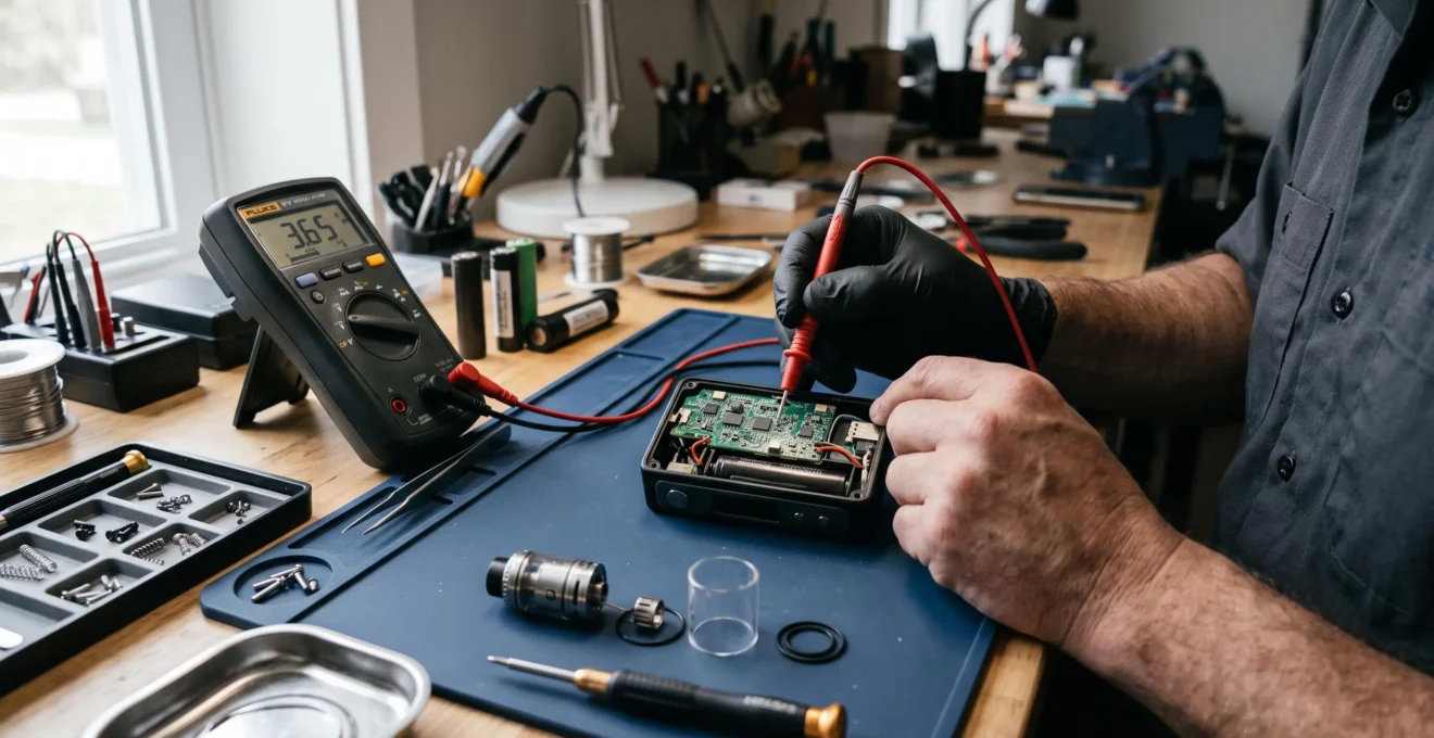
An electronic cigarette circuit board determines how a regulated vape turns battery energy into controlled heat at the atomiser. Rather than connecting the battery directly to the coil, the board monitors electrical conditions, adjusts power delivery and interrupts operation when certain faults or operating limits are detected.
This electronic control explains why a variable-wattage mod can produce a reasonably consistent heating response even as its battery voltage changes. It also explains familiar messages such as « Check Atomizer », « Weak Battery » and « Too Hot ». These warnings are not merely display features: they reflect measurements and decisions made by the device’s control electronics.
For UK vapers using regulated box mods or other adjustable devices, understanding these functions helps distinguish normal protective behaviour from a battery, atomiser or electronics fault. The important components include the power converter, semiconductor switches, resistance-sensing circuitry, control processor and user interface. Their exact arrangement varies between manufacturers, but their combined purpose is to manage the electrical energy reaching the coil within the device’s limits.
What matters inside a regulated vape
- The circuit board controls the relationship between battery voltage, coil resistance and delivered power rather than simply passing battery voltage to the atomiser.
- Its controller monitors operating conditions and can restrict or interrupt firing when it detects electrical faults, excessive temperature or insufficient battery voltage.
- Consistent wattage depends on the converter’s operating limits, battery condition, atomiser connections and the capability of the specific chipset.
- Why Does a Regulated Vape Need a Circuit Board Between the Battery and Coil?
- How Does a Vape Circuit Board Process a Puff From Button Press to Heating?
- Basic or Advanced Vape Chipset: Which Fits a Variable-Wattage Device?
- Which Vape Symptoms Can Point to a Failing Circuit Board Before Complete Shutdown?
- How Can You Reduce Stress on a Vape Circuit Board During High-Power Use?
- How Can You Trace the Electrical Path Through a Basic Vape Circuit?
- Direct Connection or Regulated Output: How Do the Two Vape Designs Differ?
- How Does a Regulated Vape Maintain Consistent Wattage as the Battery Drains?
Why Does a Regulated Vape Need a Circuit Board Between the Battery and Coil?
A regulated vape needs a circuit board because battery voltage changes during discharge while the coil requires controlled electrical power for predictable heating. The board measures relevant operating conditions, adjusts the electrical output and applies protective limits. Without regulation, the coil receives voltage determined mainly by the battery and circuit resistance, so its heating power changes as the battery discharges.
In a directly connected mechanical device, closing the switch completes a circuit between the battery and atomiser. The coil’s resistance determines the current drawn at the available battery voltage, subject to additional resistance in the battery, contacts and wiring. As the battery discharges, its terminal voltage generally falls, reducing the power available to the same coil.
A regulated mod adds an electronic power-conversion stage. Depending on its design, this stage can reduce voltage, increase voltage or provide both functions. The controller adjusts the converter’s operation to approach the selected wattage rather than allowing the coil’s output to follow battery voltage directly.
The Evolv DNA 75 technical manual provides a concrete example. It describes the DNA 75 as a regulated switch-mode DC-DC converter with a declared output range of 1–75 W, a battery input range of 3.0–4.2 V and an output-voltage range of 0.2–6.2 V. These are specifications for that board, not universal limits for regulated vapes.
The electronic board simultaneously performs three distinct jobs:
- Power conversion: it controls the electrical output supplied to the atomiser within the converter’s capabilities.
- Electrical protection: it monitors conditions that may require firing to be limited or stopped.
- User control: it interprets settings and communicates information through buttons, displays or other interface components.
Low-resistance coils make this control particularly important because modest changes in voltage can produce substantial changes in current and heating power. Regulation does not eliminate battery limitations, but it helps prevent ordinary variations in battery charge from translating directly into unpredictable coil power.
Once this distinction is clear, the next question is how the board coordinates its measurements and switching operations during an individual puff.
How Does a Vape Circuit Board Process a Puff From Button Press to Heating?
When a regulated vape detects a fire-button press or draw-sensor signal, its controller evaluates the request, checks relevant electrical conditions and enables power delivery if operation is permitted. The circuit then controls the energy supplied to the coil until the user releases the button, the draw ends or a protective condition interrupts firing. The exact measurement sequence depends on the chipset.
The process begins with a low-power control signal rather than the firing button necessarily carrying the atomiser’s full current. On the DNA 75, for example, the manufacturer identifies separate button connections and specifies that semiconductor transistors handle power switching inside the module.
A typical regulated firing cycle can be understood as the following sequence:
- Input detection: the controller recognises the fire command from a button or compatible activation sensor.
- Condition checks: the electronics evaluate battery status, atomiser connection and relevant operating limits.
- Load assessment: resistance information obtained from the atomiser helps determine suitable output conditions.
- Power activation: the converter and switching transistors deliver controlled electrical energy to the coil.
- Output management: the controller adjusts or constrains delivery according to its operating mode and detected conditions.
- Termination: heating stops when the activation request ends or a protective condition requires shutdown.
Not every board takes a completely new resistance measurement before every puff. Some detect a new atomiser or changes to the connected load and update their calculations accordingly. The DNA 75 documentation specifically describes checking whether an atomiser has been changed.
An oxidised connector, loose atomiser or contaminated 510 contact can interfere with the electrical connection. An incorrect resistance reading can influence calculated output requirements or cause the controller to reject the firing request. A sensible external check is to compare the displayed resistance when the atomiser is securely attached and after inspecting and cleaning accessible contacts with the device switched off.
The actual heating current is controlled by semiconductor power switches, commonly MOSFETs, working within the converter architecture. Rapid switching and associated circuitry allow the regulator to manage output without relying on a simple permanently closed connection to the battery.
Safety checks remain active throughout relevant parts of this process. A detected short circuit can prevent activation, a battery-voltage problem can limit or stop output, and an over-temperature condition can shut the board down. Some devices also impose a maximum firing duration, although a universal timeout cannot be assumed.
The reliability of that sequence depends on the capabilities of the chipset, which is why two adjustable mods can behave differently despite apparently similar settings.
Basic or Advanced Vape Chipset: Which Fits a Variable-Wattage Device?
A basic vape chipset can be suitable when the device only needs adjustable wattage, dependable atomiser detection and appropriate electrical protections. An advanced chipset becomes more relevant when the user needs temperature-related functions, configurable preheat, more detailed feedback or tighter control across demanding operating conditions. The better choice depends on actual features and verified performance, not the complexity of the display.
For a straightforward variable-wattage setup, the most important characteristic is whether the electronics can deliver the requested power reliably across the intended coil-resistance and battery-voltage ranges.
A more sophisticated board may offer additional control algorithms, settings or diagnostic information. However, the presence of advanced modes does not establish superior performance unless the hardware can support them under real operating conditions.
The following comparison identifies practical selection criteria rather than assigning capabilities to every product in a chipset category.
| Selection criterion | Basic chipset | Advanced chipset |
|---|---|---|
| Variable wattage | Suitable when its stated operating range meets the intended load | May provide additional control and configuration options |
| Temperature protection | May be absent | May support compatible coil materials and appropriate operating modes |
| Preheat and power profiles | Often limited or unavailable | May allow adjustable initial power or delivery profiles |
| Display and diagnostics | Basic settings and warning indications | Potentially more detailed monitoring and error information |
| High-demand operation | Depends on the converter, battery and current limits | Also limited by hardware ratings and thermal conditions |
The DNA 75 illustrates how several capabilities can coexist: variable wattage, battery monitoring, preheat, temperature protection for suitable coils and an OLED interface. These features make it a useful technical example, but they do not establish that every similarly described chipset offers identical functions.
Temperature-related operation also requires care in interpretation. Compatible systems can estimate changes in coil temperature from resistance behaviour, but this is not equivalent to every device directly measuring the coil’s temperature with a dedicated sensor.
Advertised maximum wattage is not a promise of constant availability. Output-voltage limits, continuous-current ratings, battery condition and converter performance may restrict what a device can actually deliver. A high maximum-power figure therefore needs to be considered alongside the intended atomiser resistance.
Similarly, a more detailed battery indicator is not necessarily a more accurate one. Its usefulness depends on the underlying measurement and reporting method. Independent performance testing, where available, provides stronger evidence than an attractive specification sheet alone.
A capable chipset should also communicate problems clearly. Understanding those warnings helps distinguish genuine electronics faults from issues elsewhere in the device.
Which Vape Symptoms Can Point to a Failing Circuit Board Before Complete Shutdown?
Possible signs of a failing vape circuit board include repeated unexplained error messages, unstable resistance readings, irregular power delivery, display faults and firing that stops unexpectedly. However, these symptoms do not prove that the board has failed. Battery deterioration, contaminated contacts, damaged coils and poor atomiser connections can produce similar behaviour and should be considered before concluding that the electronics need replacement.
A meaningful diagnosis begins by separating what the device reports from what is physically happening. A working screen with no coil heating, for example, shows that at least part of the control electronics is operating, but it does not establish that the power-conversion stage is healthy.
Some regulated boards distinguish between connection problems, short circuits, insufficient battery power and excessive internal temperature. The DNA 75 documentation describes messages including « Check Atomizer », « Shorted », « Weak Battery », « Check Battery » and « Too Hot ». Their interpretation is specific to that device’s control logic.
Where the device appears otherwise safe, a non-invasive elimination process can help narrow down the fault:
Five checks before suspecting the circuit board
- Record the exact warning message or abnormal behaviour and when it occurs. The result is a written symptom record rather than an assumption about the cause.
- Switch the device off and inspect the accessible atomiser and 510 contacts for visible contamination or damage. Record whether a connection problem is visible.
- Check the installed coil and atomiser against the manufacturer’s compatibility instructions. Note any clear mismatch or deterioration.
- If the equipment is compatible and safe to use, compare the atomiser with another known-working regulated mod, or a known-working atomiser with the affected device. Record which combination reproduces the fault.
- Compare the observations with the manufacturer’s error guidance and determine whether the issue remains device-specific. The outcome is a documented decision to resume normal use, seek professional inspection or retire the device.
A failure occurring only at higher output may indicate inadequate battery capability, voltage sag, a current limit or a thermal protection event. A fault appearing during charging may concern the charging system or battery condition rather than the coil-output stage. Neither pattern independently proves circuit-board damage.
Stop using the device immediately if it develops abnormal heat, a burning smell, visible electrical damage or repeated short-circuit warnings with a known-sound atomiser. Do not continue repeated firing attempts to confirm the diagnosis. A damaged or swollen battery requires equally cautious handling according to the manufacturer’s instructions.
If the device is functioning normally, reducing unnecessary thermal and electrical strain becomes a more useful priority than attempting to investigate its internal components.
How Can You Reduce Stress on a Vape Circuit Board During High-Power Use?
To reduce stress on a vape circuit board during high-power operation, keep the device within its specified electrical limits, avoid excessive heat accumulation and maintain sound battery and atomiser connections. High output power requires the converter and switching components to handle substantial electrical energy, producing internal losses. Repeated heavy operation can increase thermal demands, although the effect on component lifespan depends on the board’s design and operating conditions.
The coil resistance and selected wattage jointly determine the output voltage and current required at the atomiser. Higher requested power increases the energy the converter must transfer, while lower resistance at a given wattage requires greater output current.
Because conversion is not perfectly efficient, some electrical energy becomes heat within the electronics. As a manufacturer-declared example, the DNA 75 documentation lists typical efficiency of 85%. That figure is not a universal efficiency rating, nor does it establish the precise heat generated under every operating condition.
Two types of stress need to be distinguished:
- Thermal stress: heat accumulated in the converter, switching components or surrounding enclosure, particularly when cooling time is limited.
- Electrical stress: current, voltage or fault conditions that approach or exceed the ratings of components or connections.
Long or closely repeated activation periods may give the device less opportunity to dissipate heat. Allowing a warm device to cool and respecting its protective temperature warnings are sensible precautions. A coil showing abnormal resistance behaviour should be checked or replaced rather than compensated for through increasing wattage.
Battery selection matters as well. A cell unsuitable for the required current can experience excessive voltage sag or heating. For multi-cell devices, users should follow the manufacturer’s requirements for compatible and appropriately matched batteries.
The FDA guidance on preventing vape battery fires and explosions recommends following manufacturer instructions, using specified batteries, avoiding mixed battery types or charge states, and keeping devices away from extreme temperatures. It also advises charging on a clean, flat surface away from flammable materials where the device can be observed.
These measures primarily address battery and device safety. They should not be presented as proven methods of extending a particular chipset’s service life. Nevertheless, avoiding excessive heat and inappropriate battery conditions reduces circumstances in which the electronics must manage difficult or potentially hazardous operation.
Understanding where the electrical current actually travels helps explain why these maintenance practices affect different parts of the device.
How Can You Trace the Electrical Path Through a Basic Vape Circuit?
The electrical path through a basic regulated vape begins at the battery, passes through power-management and switching circuitry, reaches the atomiser through its output connection and returns through the corresponding electrical conductors. The chipset controls this path using separate low-power signals and measurements. Following these functions helps explain a fault, but the internal circuit should not be probed or opened by an untrained user.
A simplified functional path can be represented as follows:
Battery → power converter and switching stage → output connector → coil → electrical return.
The controller, sensors, firing switch and display form associated control circuits. Their role is to measure conditions and instruct the power electronics rather than necessarily carrying the substantial current supplied to the coil.
In a practical mod, the physical order of components may differ from this simplified representation. MOSFETs, inductors, capacitors and sensing components can occupy different positions depending on the converter topology. The drawing is therefore a functional model, not an internal schematic applicable to every device.
This distinction also helps explain why an illuminated display does not guarantee coil heating. A functioning user interface may still coexist with an interrupted atomiser connection, a protective lockout or a fault in the high-current stage.
For professional technicians, circuit diagnosis may involve checking battery input, regulated output and connection continuity against the manufacturer’s electrical documentation. Such testing requires appropriate isolation, equipment and competence, particularly around lithium-ion cells.
For the ordinary user, the same reasoning can be applied without electrical measurements. Check the device’s displayed battery condition, inspect accessible atomiser contacts while powered off and note whether a compatible atomiser is recognised. These observations can indicate which functional stage warrants professional attention.
Do not attempt continuity testing on an energised device, bridge connector contacts or expose battery terminals to test the power stage. Removing a battery, where the product is designed for it, does not necessarily make every internal electronic component safe to handle.
The distinction between controlled conversion and a direct battery connection becomes particularly clear when the two architectures are compared side by side.
Direct Connection or Regulated Output: How Do the Two Vape Designs Differ?
A directly connected vape supplies the coil from the battery through a comparatively simple switching path, so available coil voltage follows battery conditions and circuit losses. A regulated vape introduces electronic conversion and control to adjust output power and monitor faults. The practical difference is predictable power delivery and documented protective functions, balanced against the additional complexity and limitations of the electronic circuitry.
In a mechanical design, the coil’s resistance and the battery’s available voltage largely determine electrical power. There is no variable-wattage controller actively maintaining a selected output. Consequently, the same installed coil can heat differently as the battery discharges.
A regulated design measures or estimates the electrical conditions needed to achieve the selected settings. Provided that the operating limits are not exceeded, the power-conversion stage can compensate for changing battery voltage.
| Characteristic | Direct connection | Regulated output |
|---|---|---|
| Coil voltage | Follows battery terminal voltage and circuit losses | Electronically controlled within converter limits |
| Power adjustment | Depends on battery conditions and coil resistance | May offer user-selectable wattage |
| Electrical protection | Mechanical devices generally lack chipset-based safeguards | Protection features depend on the specific design |
| Consistency during discharge | Power normally decreases as voltage falls | Can compensate until an operating limit is reached |
| Electronic complexity | Relatively few control components | Converter, controller, sensors and switching electronics |
| Low-resistance operation | Requires careful compatibility with the battery and current path | Constrained by supported resistance, voltage and current ranges |
A direct connection is not automatically a simpler version of a safe regulated device. Without electronic monitoring, the user cannot assume automatic protection against short circuits, excessive current or unsuitable battery conditions. Coil resistance must remain compatible with the entire electrical system, and exceeding component ratings can create serious hazards.
Regulated devices reduce the need for users to manage some electrical variables themselves, but electronic protections are not guarantees against malfunction. Battery damage, poor connections and manufacturing faults remain possible.
The architecture choice therefore has practical implications beyond convenience. A mechanical device offers a more direct electrical arrangement but places greater demands on the user’s understanding of battery and coil compatibility. A regulated device offers adjustable behaviour and protective monitoring, provided it is used according to its specifications.
For a regulated device, the remaining question is how effectively that control can compensate for declining battery voltage without exceeding the converter’s physical limits.
Key takeaways before checking wattage stability
- A stable wattage setting is only achievable while the battery and converter can supply the necessary voltage and current.
- Coil resistance changes the output voltage required for a particular wattage, even when the displayed power setting stays the same.
- Weak-battery warnings and unexpected output reductions should be interpreted alongside battery condition, atomiser resistance and the device’s documented operating range.
How Does a Regulated Vape Maintain Consistent Wattage as the Battery Drains?
A regulated vape maintains wattage by controlling the electrical output delivered to the coil as battery voltage changes. A suitable DC-DC converter adjusts its switching operation to produce the voltage required for the selected power and measured load. Regulation continues only while the battery, converter and atomiser remain inside their permitted operating ranges; beyond those limits, the chipset may reduce power or stop firing.
In power electronics, a buck converter reduces input voltage while a boost converter increases it. A buck-boost architecture can accommodate situations in which the required output voltage is either below or above the available input voltage.
The Texas Instruments application brief on buck, boost and buck-boost converters explains these operating principles and the role of switching devices in voltage conversion. It describes general power-converter engineering, not the internal topology of every vape chipset.
The relationship between coil resistance, output voltage, current and power follows these electrical equations:
- Power: P = V × I
- Ohm’s law: V = I × R
- Resistive load power: P = V² / R
Here, P represents electrical power in watts, V represents voltage, I represents current in amperes and R represents resistance in ohms. These relationships provide a useful approximation for a resistive heating coil and a suitable representation of its electrical operating conditions.
Hypothetical example: why coil resistance changes the required voltage
Consider an illustrative regulated device set to 40 W. If its coil resistance is assumed to be 0.5 ohm, the simplified resistive-load relationship gives a required output voltage of approximately 4.47 V and a current of approximately 8.94 A.
If a different coil has an assumed resistance of 1.0 ohm at the same 40 W setting, the required voltage rises to approximately 6.32 V while output current falls to approximately 6.32 A. These values are mathematical illustrations, not measurements from a specific vape.
Whether either configuration can operate depends on the actual device’s supported voltage, output-current and resistance limits. The board cannot provide a voltage simply because the calculation requires it.
The converter also has to draw sufficient electrical energy from the battery. As battery voltage falls, maintaining a given output power can require greater input current, with additional demand arising from conversion losses. Eventually, a voltage, current, thermal or battery-protection limit may prevent the selected wattage from being maintained.
The DNA 75 provides a documented example of this behaviour: its « Weak Battery » message may appear while the device continues operating at less than the requested wattage. Its separate « Check Battery » condition can prevent firing when the battery is deeply discharged or damaged.
To assess regulation in normal use, observe whether the device recognises the atomiser consistently, whether warnings appear as charge falls and whether heating behaviour changes unexpectedly at an otherwise unchanged setting. Flavour, vapour production and perceived warmth alone cannot accurately measure output wattage, because coil condition and liquid delivery also influence the result.
Accurate confirmation of electrical performance requires suitable independent testing equipment and procedures. It should not involve measuring exposed live connections on a consumer device.
Check the manufacturer’s supported resistance range, output ratings and battery requirements for the specific mod. If the device repeatedly fails to maintain its settings or displays unexplained warnings, stop troubleshooting through repeated firing and seek an appropriate professional assessment.
Can a vape circuit board work even when its screen is damaged?
Some control and power-management functions may remain operational despite a display fault because the screen and high-current circuitry perform different functions. However, a working or partially working device should not be assumed safe when its status information is unavailable. Follow the manufacturer’s instructions and seek qualified inspection rather than continuing to use equipment with an unexplained display failure.
Does every regulated vape use a buck-boost converter?
No universal converter topology can be assumed. Regulated devices can employ different electronic arrangements according to battery configuration, intended output range and manufacturer design. Buck, boost and buck-boost describe established voltage-conversion principles, but identifying the topology inside a particular vape requires its technical documentation or reliable engineering evidence.
Can a dirty 510 connector cause an incorrect resistance reading?
Yes. Contamination, oxidation or poor physical contact can interfere with the electrical connection between the atomiser and mod, potentially contributing to unstable readings or connection errors. Switch the device off before inspecting accessible contacts, follow the manufacturer’s cleaning guidance and avoid damaging the connector. Persistent faults warrant further assessment.
Does a regulated chipset make a damaged lithium-ion battery safe to use?
No. Electronic battery monitoring and protective shutdowns cannot guarantee that a damaged or unsuitable lithium-ion cell will operate safely. Batteries with physical damage, abnormal heating or other warning signs should not be used. The device manufacturer’s battery-selection, handling and replacement instructions remain essential regardless of the chipset’s protection features.
Can a vape circuit board be replaced instead of buying another mod?
Replacement depends on the device’s construction, component availability and manufacturer support. Some boards are designed for integration into compatible hardware, while many consumer mods are not intended for user-level electronics repair. A replacement must match the device’s electrical, mechanical and control requirements. Improvised board substitutions or lithium-ion wiring repairs are not appropriate consumer troubleshooting methods.