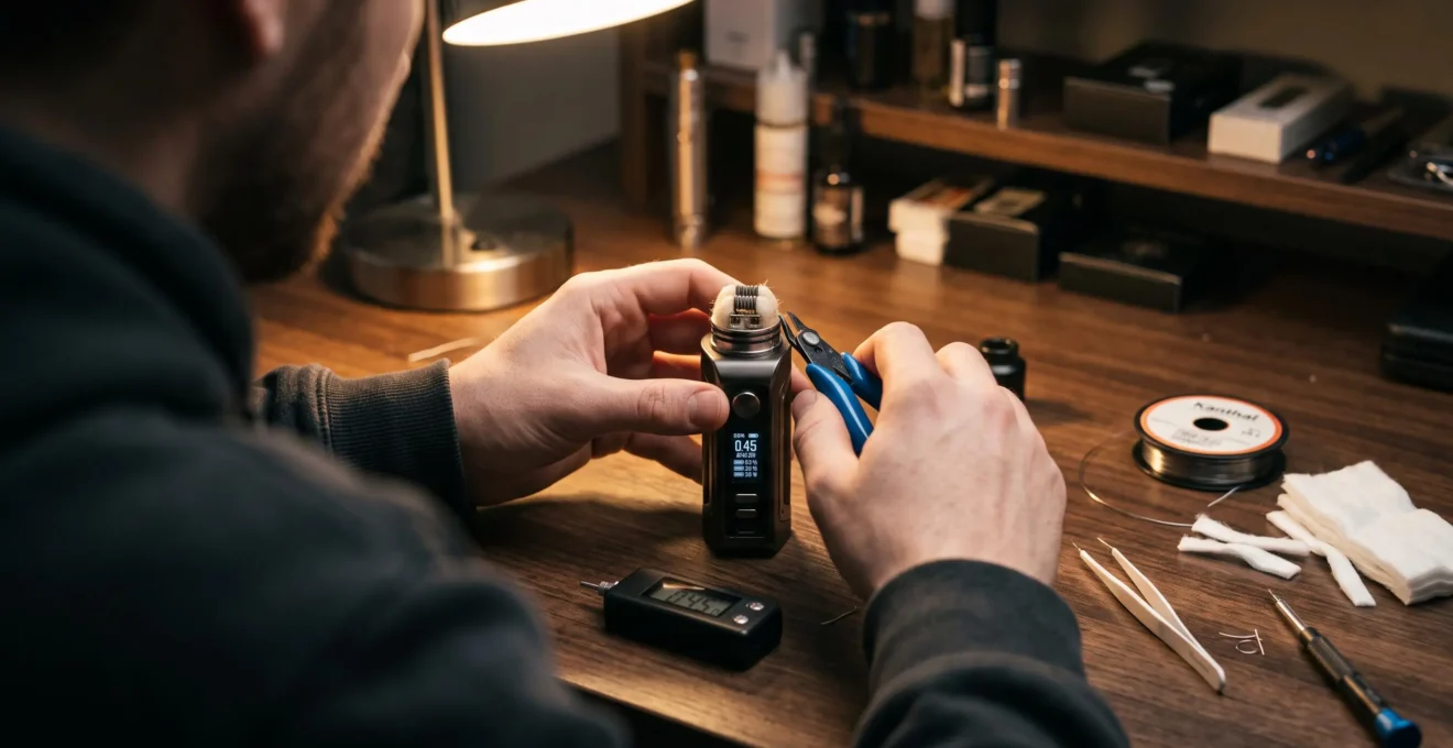
Electrical resistance determines how a vape coil responds to the voltage applied across it. Measured in ohms (Ω), resistance controls the relationship between voltage, current and electrical power. Those relationships explain why some coils require higher currents, why others need higher voltages and why the same wattage setting can produce different heating behaviour.
The distinction between regulated and unregulated devices is essential. With a fixed voltage across a coil, lowering resistance increases current and power. On a regulated mod operating in wattage mode, the electronic circuit instead adjusts its output to maintain the selected power, provided the coil remains within the device’s electrical limits.
Resistance is therefore more than a number displayed on a screen. It provides information about electrical compatibility, potential faults and the demands placed on the device’s output circuitry. Understanding it also helps explain how coil construction, thermal mass and airflow interact with heating performance.
Vape Coil Resistance: The Essential Electrical Relationships
- At a fixed voltage across the coil, lower resistance increases current and electrical power according to Ohm’s law.
- At a fixed wattage on a regulated mod, resistance changes the required output voltage and current rather than automatically changing delivered power.
- Coil resistance must remain compatible with the device’s operating limits, and unexpected readings should be investigated before use.
- Why Does Lower Coil Resistance Change Electrical Demand in a Vape?
- How Can You Check Coil Resistance Before Using a Rebuildable Atomiser?
- Higher or Lower Coil Resistance: How Does Each Affect a Regulated Vape?
- Why Is a Sudden Change in Coil Resistance a Warning Sign?
- How Can You Match Coil Resistance to a Device’s Supported Operating Range?
- How Can You Confirm Coil Resistance Before Normal Vape Use?
- Why Are Voltage, Current and Resistance Linked in a Vape Circuit?
- How Does Coil Resistance Influence Vape Performance on a Regulated Device?
Why Does Lower Coil Resistance Change Electrical Demand in a Vape?
Lower coil resistance allows more electrical current to flow when the voltage across the coil remains constant. Because electrical power depends on both voltage and current, reducing resistance under those conditions also increases the power converted into heat. On a regulated vape, however, the effect depends on whether the device maintains a fixed voltage or a selected wattage.
Ohm’s law expresses the relationship as V = I × R, where V represents voltage, I represents current and R represents resistance. Rearranging the equation gives I = V / R. For an approximately ohmic heating element, electrical power can be expressed as P = V × I or P = V² / R.
These relationships are established in OpenStax‘s university physics explanation of electrical power, which describes how energy dissipated across resistance becomes thermal energy.
Consider an explicitly hypothetical comparison in which two coils each receive a constant 4 V:
Hypothetical Example: Two Coils at the Same Voltage
A 1.0 Ω coil receiving 4 V carries 4 A and dissipates 16 W. A 0.5 Ω coil receiving the same voltage carries 8 A and dissipates 32 W.
Halving the resistance doubles both current and power in this constant-voltage example. These are calculated illustration values, not measurements from a particular vaping device. Actual coil temperature also depends on heat loss, material, geometry and operating conditions.
This explains the increased electrical demand associated with low-resistance coils on circuits that do not compensate by changing voltage. Higher current creates greater demands on the electrical path, including conductors and contacts, while increased power can produce faster heating if the coil’s thermal properties remain comparable.
Importantly, resistance does not consume power independently. It determines the current that flows at a particular applied voltage. The resulting electrical power is converted primarily into heat in the coil.
Regulated wattage mode changes the comparison. If the mod successfully maintains 20 W, the coil receives approximately 20 W whether its resistance is 0.5 Ω or 1.0 Ω. The output voltage and current differ, but lower resistance does not automatically mean higher power.
Battery demand must also be considered separately. A regulated mod contains a power converter, so coil current is not necessarily battery current. At a similar battery voltage and conversion efficiency, battery input power depends mainly on the delivered wattage rather than directly on coil resistance.
The practical trade-off is between coil-side current, attainable power and the characteristics of the heating element. Resistance establishes the electrical conditions, while the device’s regulation and the coil’s physical construction determine how those conditions translate into operation.
How Can You Check Coil Resistance Before Using a Rebuildable Atomiser?
Check a rebuildable atomiser’s resistance before firing it by mounting the completed build on a suitable dedicated ohm reader or compatible regulated mod and examining the displayed value. Compare that reading with the resistance expected from the coil design. If the result is unexpectedly low, unstable or outside the device’s supported range, investigate the build before applying power.
A rebuildable atomiser introduces electrical variables that are normally controlled during the manufacture of a replaceable coil. Wire length, wire material, post connections and accidental contact with the deck can all influence the measured resistance.
A practical pre-use inspection follows these steps:
- With the device unpowered, inspect the coil for unintended contact with the atomiser deck, chamber or other conductive surfaces.
- Ensure the coil legs are properly secured in their intended connections and that no loose wire ends extend into unintended contact points.
- Mount the atomiser on a suitable resistance reader or compatible regulated device without activating the heating function.
- Read the displayed resistance and compare it with the expected value for the wire material, dimensions and configuration.
- If the value is plausible and stable, complete the remaining manufacturer-recommended checks before normal use. Repeat the resistance check after wicking, reassembly and any subsequent adjustment.
The expected reading does not need to match a calculated nominal value perfectly. Wire manufacturing tolerances, contact resistance and measurement resolution can produce modest differences. However, a large discrepancy should not be dismissed as normal variation.
An unexpectedly low reading may indicate unintended contact between conductive components, including a coil touching the deck or chamber. An unexpectedly high or fluctuating reading may suggest a loose connection or additional resistance in the electrical path. The measurement identifies a condition requiring investigation; it does not prove a particular defect by itself.
For a mechanical device, battery compatibility is especially important because the device does not provide the same electronic power regulation and protective functions as a regulated mod. A measured resistance must never be treated as safe without checking the applicable battery specifications and the entire electrical configuration.
The U.S. Food and Drug Administration‘s FDA Grand Rounds material on electrical safety in vaping products identifies high current draw, interchangeable cells and limited protective controls among the relevant electrical hazards. The document does not establish a universal safe coil resistance or battery discharge rating.
After installation and any manufacturer-permitted inspection or adjustment, check the resistance again. Coil legs can shift, assembly pressure can change contacts, and a chamber installed over the build may introduce unintended contact that was not present during the initial measurement.
If a build cannot produce a stable, compatible reading, stop using it until the cause has been resolved. A resistance check is a diagnostic step, not permission to exceed device or battery limits.
Higher or Lower Coil Resistance: How Does Each Affect a Regulated Vape?
On a regulated vape set to a fixed wattage, lower resistance requires less output voltage but more coil current, while higher resistance requires more voltage and less current. Provided the mod operates within its specifications, both coils can receive the selected power. Their actual heating characteristics still depend on coil construction, thermal mass, airflow and liquid supply.
At a target power P, the required output voltage is V = √(P × R), while coil current is I = √(P / R). These relationships show why a regulator must accommodate different electrical conditions as resistance changes.
The comparison below assumes the same desired wattage and a device capable of supplying it.
| Characteristic | Lower-resistance coil | Higher-resistance coil |
|---|---|---|
| Required voltage at equal power | Lower | Higher |
| Output current at equal power | Higher | Lower |
| Typical coil designs | Often associated with higher-power, open-airflow configurations | Often associated with lower-power, restricted-airflow configurations |
| Possible device limitation | Maximum output current | Maximum output voltage |
| Heating at equal wattage | Depends on thermal mass, geometry and cooling | Depends on thermal mass, geometry and cooling |
The electrical relationship does not dictate vaping style. Low-resistance coils are often designed with larger heating surfaces and wider airflow for direct-lung use, while higher-resistance coils commonly appear in lower-power, mouth-to-lung systems. These are design tendencies, not universal physical rules.
Two coils with identical resistance may contain different amounts of metal. A larger coil may require more energy to reach a particular temperature because more material must be heated. Airflow and e-liquid evaporation also remove heat during operation.
Conversely, two coils with different resistance values may respond similarly when their thermal mass and supplied power are appropriately matched. Resistance alone cannot establish which coil heats faster or produces more aerosol.
Another important distinction is between selected and delivered wattage. A regulated device can maintain its setting only while its voltage, current and other operational limits allow it. Outside those limits, the displayed target may not equal the actual electrical output.
Coil choice should begin with the manufacturer’s compatibility information and intended operating range, followed by the coil’s physical design and airflow requirements. Resistance supplies one essential measurement, but it cannot substitute for those specifications.
Why Is a Sudden Change in Coil Resistance a Warning Sign?
A sudden change in displayed coil resistance can indicate an altered electrical connection, unintended contact, a damaged heating element or a measurement problem. Small variations may occur with temperature or normal measurement tolerance, but an abrupt or persistent shift deserves attention. Stop firing the device until the reading is understood, particularly if it falls sharply or triggers a warning.
Resistance readings depend on both the heating element and the quality of its electrical connections. A stable coil can appear to change resistance when a connection loosens, a conductive surface moves or the resistance-measuring circuit detects a different path.
Possible causes include:
- Unintended electrical contact: a rebuildable coil touches the deck, chamber or another conductive part, potentially creating a lower-resistance path.
- Loose or degraded connections: post screws, atomiser contacts or connector components introduce unstable electrical behaviour.
- Coil damage: physical deformation or deterioration changes the electrical path through the heating element.
- Contamination or moisture: residue or liquid in an inappropriate location may interfere with electrical connections, although the resistance reading alone cannot establish that cause.
- Temperature-dependent resistance: some wire materials change resistance appreciably as they heat, making operating temperature and device mode important when interpreting readings.
A small, reproducible change between cold and warm readings is not equivalent to an abrupt jump during ordinary operation. Temperature-control systems may deliberately monitor resistance changes in compatible materials. An unexplained reading outside normal operating behaviour is different and requires inspection.
On rebuildable atomisers, a sudden downward shift is especially concerning because it may indicate an unintended conductive path. Removing power and visually checking the build is more appropriate than repeatedly firing to see whether the problem disappears.
Connection faults are not always confined to the coil. A damaged or contaminated 510 connection can produce problems across different compatible atomisers. If unusual readings occur with more than one known-compatible atomiser, the device’s connector or measurement circuitry may require professional inspection.
Manufacturer warnings provide useful additional context. A short-circuit warning identifies a detected electrical condition, but it does not necessarily reveal the precise location or physical cause of the fault.
Where a fault cannot be identified and safely resolved, discontinue use and consult the manufacturer’s instructions or a qualified service provider. A device that appears to operate despite unstable resistance should not be assumed safe.
How Can You Match Coil Resistance to a Device’s Supported Operating Range?
To match coil resistance with a regulated device, compare the coil’s measured resistance against the manufacturer’s supported range, then verify that the device can supply the voltage and current needed for the intended wattage. Passing the minimum-resistance requirement alone does not guarantee that every power setting is available. Output voltage, current and power limits must all be respected.
Three electrical limits are particularly relevant: the accepted atomiser resistance, the maximum output voltage and the maximum output current. Some devices also impose different limits according to operating mode or coil material.
Evolv’s DNA 75C provides a documented example of these interacting constraints. Its manufacturer’s specifications describe a regulated DC-DC converter with an output-power range of 1–75 W, an output-voltage range of 0.2–9.0 V and a maximum continuous output current of 30.0 A.
0.02–8.0 Ω
The DNA 75C’s documented absolute cold atomiser-resistance limits. These are not a guarantee that every resistance within the interval supports every selectable wattage. Its practical output range also depends on other electrical limits and the finished device configuration.
These specifications apply to that particular electronic module and should not be generalised to all regulated mods. The manufacturer also provides resistance-dependent output-power information, illustrating why a permitted resistance value is only the first compatibility test.
For a hypothetical 40 W target, the required electrical output can be calculated as follows:
| Coil resistance | Required coil voltage | Required coil current |
|---|---|---|
| 0.2 Ω | Approximately 2.83 V | Approximately 14.14 A |
| 0.5 Ω | Approximately 4.47 V | Approximately 8.94 A |
| 1.0 Ω | Approximately 6.32 V | Approximately 6.32 A |
| 2.0 Ω | Approximately 8.94 V | Approximately 4.47 A |
These figures follow V = √(P × R) and I = √(P / R). They describe the output required at the coil, not the current supplied by the battery. Actual compatibility also depends on manufacturer-defined power restrictions, operating mode and protections.
When an electrical limit is reached, devices may respond differently. The DNA 75C documentation describes resistance-related messages such as « Ohms Too Low » and « Ohms Too High », with circumstances in which the module may continue operating without reaching the selected wattage.
Other products may refuse to activate or display different warnings. Pod systems, replaceable-coil tanks and rebuildable decks can also have separate compatibility requirements, even when they connect to the same host device.
The manufacturer’s specification for the exact device and coil configuration remains decisive. Mathematical compatibility is necessary for understanding electrical behaviour, but it does not override published operating instructions or safety restrictions.
How Can You Confirm Coil Resistance Before Normal Vape Use?
Before normal use, confirm that the coil resistance shown by a compatible regulated device approximately matches the rating stated on the installed coil or its packaging. Repeat this check after replacing a coil, reinserting a pod or cleaning accessible contacts. A missing, implausible or unstable reading should be investigated before operating the device.
Unlike the detailed inspection of a rebuildable assembly, routine resistance confirmation for a factory-made coil is primarily a compatibility and contact check. The manufacturer has already specified the nominal resistance and intended operating conditions.
For example, a coil marked 0.8 Ω should produce a reading reasonably consistent with that nominal value, allowing for measurement resolution, manufacturing tolerance and temperature. The exact acceptable deviation cannot be established universally without the manufacturer’s specifications.
Several display conditions deserve different interpretations:
- A plausible, stable value: consistent with the coil rating and within the supported device range.
- No detected resistance: potentially an open circuit, improperly seated coil, connection problem or unsupported atomiser.
- A zero or near-zero reading: potentially a short or measurement condition requiring investigation; the precise meaning depends on the device.
- A sharply different or unstable value: a possible seating, connection, component or sensing issue that should not be ignored.
For devices without a numerical resistance display, the manufacturer’s coil compatibility information becomes particularly important. Error messages, refusal to fire and documented protection behaviour may reveal a problem, but the absence of a warning is not proof that every connection is sound.
Aspire’s Flexus Pro provides an example of device-specific warnings. Its manual documents separate open-circuit, low-resistance and short-circuit protections, including messages such as « Check Atomizer », « Low Res » and « Atomizer Short ». These labels cannot be assumed to apply to other devices.
The manufacturer describes these protections in Aspire’s Flexus Pro user manual. Users should consult the documentation for their own equipment rather than interpreting all resistance errors as interchangeable.
After routine maintenance, make sure the coil or pod is seated according to the manufacturer’s instructions, confirm that the device recognises it and check for any persistent alerts. Do not bypass a protection warning to force operation.
Routine confirmation cannot detect every possible defect. It is one part of normal equipment inspection, alongside following the manufacturer’s operating, maintenance and battery safety instructions.
Why Are Voltage, Current and Resistance Linked in a Vape Circuit?
Voltage, current and resistance are linked because the current through an approximately ohmic vape coil depends on the voltage applied across its electrical resistance. Electrical power is then converted into heat within the coil. Ohm’s law describes these relationships, while the device’s regulation determines which electrical quantity is controlled during operation.
Voltage describes electrical potential difference, current describes the rate of electric charge flow and resistance describes opposition to that current. In an approximately resistive heating element, the three quantities follow V = I × R.
Combining that relationship with P = V × I gives two additional forms: P = I² × R and P = V² / R.
Each equation answers a different question. At a fixed voltage across the coil, resistance determines current and power. At a fixed current, increasing resistance increases the power dissipated in that resistance. At a fixed target wattage, both the required voltage and current depend on resistance.
A vape coil acts as a resistive heating element. As electrical energy becomes thermal energy, the wire temperature rises until the heat input is balanced by heat transfer to surrounding materials and the environment. During operation, some heat is transferred to e-liquid and supports aerosol formation.
That process depends on more than electrical power. Heat conduction, airflow, liquid availability, wire mass, geometry and temperature-dependent resistance influence the resulting coil temperature. An equation for electrical power does not independently predict aerosol output or a particular operating temperature.
Regulated devices introduce an additional distinction: the battery circuit and coil circuit can operate at different voltages and currents. A DC-DC converter transfers energy between the battery and atomiser while adjusting the electrical output.
In a simplified regulated system, battery input power is approximately the coil output power divided by conversion efficiency, with any additional device consumption considered separately. Therefore, coil current cannot be substituted directly for battery current.
For an explicitly hypothetical idealised case, a device delivering 40 W at 80% conversion efficiency would require approximately 50 W of electrical input, excluding other consumption. The 80% figure is a scenario assumption, not an efficiency specification for a particular vaping device.
If battery voltage changes, the input current required to supply that power can change as well. This is one reason electrical calculations for mechanical setups cannot be transferred unchanged to regulated power systems.
The equations provide a framework for checking electrical compatibility. The actual operating limits, temperature behaviour and protective responses must still come from the relevant device documentation.
Key Takeaways Before Choosing a Coil
- Check both the resistance range and the available output voltage, current and power; a resistance value alone does not establish full compatibility.
- Separate electrical output from heating behaviour: coil mass, airflow and liquid supply influence how the delivered power translates into temperature.
- Treat stable resistance readings and manufacturer-defined protection behaviour as part of the selection process, not optional checks after installation.
How Does Coil Resistance Influence Vape Performance on a Regulated Device?
On a regulated device, coil resistance influences the voltage and current required to deliver a selected wattage, while coil design determines much of the resulting heating behaviour. Lower resistance does not automatically produce faster heating or greater battery drain at equal power. Performance depends on the regulator’s limits, the coil’s thermal characteristics and the intended airflow configuration.
A useful performance assessment separates three factors: electrical compatibility, thermal response and energy demand.
Electrical compatibility determines whether the regulator can reach the desired power without exceeding its output limits. Low-resistance configurations may encounter current restrictions, while high-resistance configurations may encounter voltage restrictions.
Thermal response depends on the amount and distribution of heated material as well as the energy supplied. A coil with greater thermal mass generally requires more energy for a comparable temperature increase, all else being equal. Airflow and evaporation remove heat, changing the temperature reached during use.
Battery demand depends mainly on electrical input power and operating duration, subject to battery voltage, conversion efficiency and additional device consumption. Coil resistance can affect converter operating conditions and efficiency, but a lower resistance does not necessarily produce greater battery current when delivered wattage is held constant.
The practical distinction matters when comparing coils marketed for different airflow styles. A low-resistance coil designed for high-power, open-airflow operation may perform poorly at a wattage suited to a smaller, higher-resistance mouth-to-lung coil. The difference arises from the complete heating assembly rather than resistance alone.
Likewise, two coils intended for similar wattages may deliver different temperature profiles because they use different materials, wire dimensions, heating surface areas or airflow arrangements.
Before selecting or installing a coil, use the following five checks to turn those relationships into a verifiable compatibility decision.
Five Checks for Selecting a Compatible Regulated Vape Coil
- Identify the exact device and coil format. Record the model and whether it uses a replaceable coil, pod or compatible rebuildable atomiser.
- Verify the supported resistance range. Locate the manufacturer’s specifications and record the applicable minimum and maximum resistance values or accepted coil types.
- Check the intended operating power. Record the coil manufacturer’s wattage guidance and compare it with the device’s supported output range.
- Confirm the electrical and airflow requirements. Where output specifications are available, check voltage and current compatibility; also confirm that the coil design suits the intended airflow configuration.
- Verify the installed resistance. Record the displayed value or the device’s documented recognition status, and resolve unexpected readings or warnings before use.
The resulting checks distinguish what can be calculated from what must be confirmed using manufacturer information. They also help prevent a common mistake: assuming that a coil is appropriate simply because its resistance falls somewhere within a broad numerical range.
Temperature-control operation introduces further requirements because compatible wire materials and resistance sensing can form part of the regulation method. The device and coil manufacturer’s instructions should determine whether that mode is supported.
For the next coil change, compare the device specifications, the coil’s intended power and airflow, and the resistance actually displayed after installation. Those checks provide a more reliable technical basis for choosing a compatible setup than resistance alone.
Does a coil’s resistance stay constant while it heats up?
Not necessarily. Electrical resistance can change with temperature, and the size of that change depends on the wire material. Temperature-control systems may use this behaviour with compatible coils. A difference between cold and warm readings is therefore not automatically a fault, although unexpected instability still requires investigation.
Can two coils with identical resistance have different heating speeds?
Yes. Coils with the same resistance can differ in material, wire thickness, surface area and thermal mass. At the same delivered electrical power, these characteristics influence the rate of temperature increase, while airflow and liquid evaporation affect cooling. Resistance alone cannot reliably predict heating speed.
Why does a regulated mod sometimes deliver less than its selected wattage?
The requested power may require more output voltage or current than the device can provide at the installed coil resistance. Battery conditions or protective restrictions can also affect operation. Depending on the model, the device may reduce output, display an error or refuse to fire. The manufacturer’s operating specifications determine the applicable behaviour.
Does using a higher-resistance coil always extend battery life?
No. At the same actual wattage and operating duration, a regulated device generally requires similar battery input energy, subject to differences in conversion efficiency and other consumption. Higher-resistance coils are often used at lower power levels, which can reduce energy use, but that benefit comes primarily from the lower operating power rather than resistance alone.
Is a coil safe simply because its resistance falls within the device’s specified range?
No. A supported resistance reading is only one compatibility condition. The intended wattage, output voltage and current, coil condition, connection quality, battery requirements and manufacturer instructions also matter. A device’s protective electronics should not be treated as a guarantee against every electrical or mechanical fault.