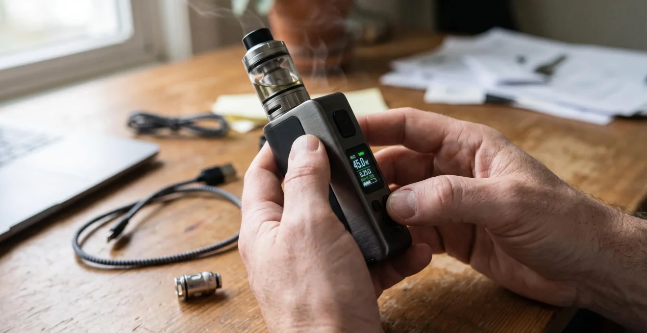
Setting a regulated vape to a particular wattage does not mean the battery sends that exact amount of electrical power directly to the coil. Between the battery and atomiser sits electronic circuitry that manages voltage, monitors electrical conditions and determines whether the requested output can be delivered.
This distinction explains why a regulated device can produce relatively consistent heating as its battery discharges, yet occasionally deliver a weaker puff without the selected wattage changing. The difference may come from the battery’s available voltage, the chipset’s operating limits, the resistance detected at the atomiser or the condition of the electrical contacts.
Understanding power delivery means separating three related measurements: battery voltage, electrical power supplied to the coil and the temperature reached by the heating element. They influence one another, but none can be inferred perfectly from the others.
For users adjusting wattage, the practical objective is not simply to select a number. It is to understand when the device can maintain that target and when its electrical or thermal limits change the heating actually produced.
Regulated Vape Power Delivery: The Essentials
- A regulated chipset converts and controls electrical output so coil power can remain relatively stable despite changing battery voltage.
- The displayed wattage may be a requested target rather than independently measured output, particularly when battery, resistance or protection limits intervene.
- Predictable heating depends on compatible coil resistance, reliable electrical contacts, sufficient battery capacity and adequate cooling between puffs.
- Why Does a Regulated Vape Need a Circuit Board Between the Battery and Coil?
- How Does a Regulated Vape Maintain Consistent Wattage as the Battery Drains?
- How Does a Vape Chip Adjust Voltage to Hold the Same Wattage?
- Why Can Vape Power Delivery Fall Below the Wattage Shown on the Screen?
- How Is Power Delivered to a Vape Coil When Resistance Changes?
- Regulated or Direct Power Delivery: Which Gives More Predictable Coil Heating?
- Which Contact Problems Cause Sudden Power Loss Between a Vape Battery and Atomiser?
- How Can You Keep Vape Power Delivery Stable During Longer Sessions?
Why Does a Regulated Vape Need a Circuit Board Between the Battery and Coil?
A regulated vape needs a circuit board because battery voltage changes during discharge, while the user expects a controlled electrical output. The board translates the selected wattage into an operating target, manages voltage conversion where supported and applies protective limits. Without that regulation, coil power would vary with the battery’s available voltage and the electrical resistance of the circuit.
A lithium-ion cell does not maintain one constant terminal voltage throughout its useful charge range. Its voltage changes with state of charge and also falls temporarily under electrical load. If a fixed-resistance heating coil is connected directly to the battery, the power dissipated in that coil depends on the voltage reaching it.
The basic relationship is P = V²/R, where P is power in watts, V is voltage across the coil and R is its resistance in ohms. When resistance remains constant, a reduction in applied voltage produces a proportionally larger reduction in power because voltage is squared in the equation.
For a direct battery connection, this means that heating generally becomes weaker as available voltage decreases. A regulated device attempts to separate the coil’s electrical operating point from that variation.
The circuit board performs three related functions:
- Power conversion: where the circuit supports it, switching electronics raise or lower voltage to meet the required output.
- Electrical protection: the control system can refuse or interrupt operation when it detects conditions such as excessive current, low battery voltage, short circuits or excessive device temperature.
- Setting interpretation: the controller uses the selected wattage and detected load conditions to determine an appropriate output.
The underlying conversion principle is established in power electronics. The Texas Instruments TPS63070 buck-boost converter specifications describe a switching circuit capable of regulating output when the input voltage is either above or below the required voltage. This component illustrates the principle; it is not evidence that a particular vaping device uses that chip or the same topology.
Not every regulated vape can both raise and lower voltage across its entire operating range. Some designs have narrower conversion capabilities, and others rely on different arrangements of switching and protection circuitry.
A mechanical device removes the active electronic regulation layer. Its coil instead responds to the voltage available through the battery and conductive path, including losses at contacts and other circuit elements. A regulated device attempts to maintain a selected electrical operating point rather than simply exposing the coil to changing battery voltage.
That control provides the basis for repeatable heating, but it does not create unlimited output capability. As a battery discharges, the controller must work within its available voltage, current and thermal limits.
How Does a Regulated Vape Maintain Consistent Wattage as the Battery Drains?
A regulated vape maintains wattage during battery discharge by adjusting its electrical conversion process as the battery’s available voltage changes. The chipset attempts to preserve the power requested at the coil, even though the battery’s operating conditions are changing. Consistency lasts only while the required output remains within the device’s supported voltage, current, battery and thermal limits.
The first distinction is between battery-side electrical power and coil-side electrical power. These are related but not identical quantities.
Battery-side power is drawn from the cell or battery pack. Coil-side power is the energy per second delivered to the heating element. Between them, the conversion circuit consumes some energy itself, so the battery must supply more electrical power than ultimately reaches the coil.
As battery voltage decreases, a regulated converter that maintains the same output power will generally need greater battery-side current, assuming other conditions remain comparable. This additional current can increase voltage sag and electrical losses.
Consequently, the displayed battery percentage and selected wattage describe different aspects of operation. A falling battery indicator does not necessarily mean that output power is falling at the same rate.
Consider a user who selects a comfortable wattage with a fully charged battery. During ordinary discharge, that device may continue producing similar heating because the chipset compensates for the changing input voltage. The user might notice little difference until the remaining battery capacity and electrical load push the converter closer to its operational limits.
At that point, several outcomes are possible:
- The chipset reduces actual output despite the original wattage setting remaining visible.
- The device displays a low-battery or power-related warning.
- The controller interrupts firing because it cannot safely satisfy the requested demand.
The behavior depends on the specific device. There is no universal battery percentage at which regulation stops working, and a high indicated charge does not independently guarantee sufficient performance under a demanding load.
A practical consistency check is to compare normal operation shortly after charging with operation at an indicated battery level of approximately 20–30%, provided the manufacturer permits use at that level. Keep the same coil, selected wattage, airflow and puff duration. Note any error messages and whether vapour production changes noticeably.
That comparison is a user-observation test, not a laboratory measurement of output watts. Battery percentage indicators are estimates, while vapour production also depends on coil temperature, liquid supply and airflow.
When heating begins to change at lower charge levels, the next question is how the controller calculates and produces the voltage required at the coil.
How Does a Vape Chip Adjust Voltage to Hold the Same Wattage?
A vape chip adjusts output voltage by using the selected wattage and measured atomiser resistance to determine an electrical target. Its power circuitry then regulates the energy transferred to the load, typically through high-speed switching. Feedback allows the controller to respond to changing operating conditions, although the measurement frequency and control method vary between chipsets.
In ordinary wattage operation, electrical power, voltage, current and resistance are connected by Ohm’s law and the power equation:
- P = V × I
- V = √(P × R)
- I = √(P / R)
Here, P represents watts, V represents volts, I represents amperes and R represents ohms.
These relationships show why the resistance reading matters. The selected power alone does not specify the required voltage: the controller also needs information about the electrical load.
For illustration, a hypothetical 40 W target across a purely resistive 0.5-ohm load requires approximately 4.47 V across that load. If the resistance were instead 1.0 ohm, the corresponding target voltage would be approximately 6.32 V. These are ideal electrical calculations, not measurements from a particular vape.
The converter uses switching components to control energy delivery. Depending on the circuit architecture, it may adjust switching duty cycle, operating frequency or other parameters. Filtering and the load determine the resulting voltage and current behavior.
Feedback is essential because a converter cannot assume that its input voltage and electrical load remain perfectly constant. However, the exact measurement and correction sequence is manufacturer-specific. A generic description of switching regulation should not be mistaken for documentation of a particular vape chipset.
The most important complication is that measured resistance may not equal the intended coil resistance under every condition.
Resistance can change with temperature, depending on coil material. Connector problems can also alter the electrical path or cause unstable readings. If the controller calculates the required voltage from an inaccurate or unrepresentative resistance measurement, its intended power target may not correspond to the actual heating behavior of the coil.
Power regulation must also be distinguished from temperature regulation. A wattage setting controls an electrical target; it does not directly establish one uniform coil temperature.
A PLOS ONE experimental study on vaping temperature-control accuracy examined three commercially available electronic nicotine delivery systems. Researchers found discrepancies between device temperature settings and independently measured temperatures, including substantial variation along individual coils.
The study focused on temperature-control performance rather than universal wattage-control accuracy. Nevertheless, its measurements illustrate an important physical distinction: managing an electrical input does not guarantee uniform temperature throughout a heating element.
Even a properly regulated electrical supply can produce different heating behavior when coil geometry, temperature-dependent resistance, airflow or liquid conditions change.
The next issue is whether the device can actually deliver the requested electrical output once its operating limits and real-world conditions are taken into account.
Why Can Vape Power Delivery Fall Below the Wattage Shown on the Screen?
Vape power delivery can fall below the displayed wattage when the battery cannot support the requested load, the required voltage or current exceeds chipset limits, coil resistance falls outside the supported range or thermal protection reduces output. The display may continue showing the selected target rather than actual delivered power, depending on the device’s interface.
A wattage setting is fundamentally a request. Whether the displayed number represents a setpoint, an estimated output or a live measurement depends on the manufacturer’s design.
This is not merely a theoretical distinction. Laboratory characterization of regulated electronic-cigarette equipment has documented differences between selected wattage and measured electrical output.
Approximately 43 W
The reported supplied-power limit in electrical calibration experiments on a Joyetech EVIC VTC Mini. This measurement describes the tested device and experimental conditions, not a general limit for regulated vapes.
Scientific Reports study on e-cigarette electrical calibration, published in 2023.
The researchers tested several equivalent resistances in power-control mode. Reported calibration ratios differed across loads: at the 45 W setting, the ratios included 89 % with a 0.16-ohm resistance and 97.2% with a 0.51-ohm resistance, while the reported ratio reached 100% with the higher tested resistances.
These findings show that selected and delivered power can differ, and that the discrepancy can depend on resistance. They do not establish that every modern regulated device behaves similarly. The experiments also did not characterize wattage regulation throughout a complete battery discharge cycle.
For an individual device, four broad explanations deserve consideration.
- Battery limitations: the available input voltage falls under load, potentially preventing the converter from sustaining its target.
- Output limits: the requested voltage, current or power exceeds the chipset’s permitted operating range.
- Resistance incompatibility: the detected load falls outside the supported resistance range or produces an invalid reading.
- Thermal protection: internal temperature rises enough for the device to reduce or interrupt operation.
The pattern of the problem offers clues. Weak output only at low battery charge suggests a different starting point from output reduction after repeated consecutive puffs. An atomiser error immediately after changing tanks may instead indicate a compatibility or connection issue.
A simple comparison involves observing one compatible tank at a normal charge level, then checking whether behavior changes with another manufacturer-approved coil or tank. If the problem follows a particular atomiser, its coil and connections deserve attention. If the problem appears across compatible atomisers, the device or battery system may need assessment.
Use only combinations expressly supported by the manufacturer. Never bypass a protection warning, modify the electronics or substitute an incompatible battery to force a higher output.
One of the most informative variables in that diagnosis is coil resistance, because it changes the voltage and current required to achieve a given wattage.
How Is Power Delivered to a Vape Coil When Resistance Changes?
When coil resistance changes, a regulated device adjusts the voltage and current relationship needed to reach its selected wattage. At the same power, a lower resistance requires less voltage but more coil current, while a higher resistance requires more voltage and less current. Compensation works only within the chipset’s supported electrical limits.
The relationships are determined by P = V²/R and P = I²R. They show that a wattage target cannot be considered independently of the coil’s resistance.
For a hypothetical fixed 30 W output, the following ideal calculations illustrate the effect.
| Coil resistance | Required coil voltage | Required coil current |
|---|---|---|
| 0.5 Ω | Approximately 3.87 V | Approximately 7.75 A |
| 1.0 Ω | Approximately 5.48 V | Approximately 5.48 A |
| 1.5 Ω | Approximately 6.71 V | Approximately 4.47 A |
These are mathematical examples for ideal resistive loads. They are not recommended operating settings or evidence that a particular device supports these combinations.
The table also distinguishes coil current from battery current. Higher coil current at lower resistance does not automatically mean higher battery current when the chipset maintains identical output power. Battery-side demand also depends on input voltage and conversion efficiency.
Coil resistance nevertheless affects the converter’s requirements. At lower resistance, the output stage must accommodate greater load current for the same wattage. At higher resistance, the required output voltage rises. Either condition can become restrictive if the device approaches its current or voltage ceiling.
The physical heating response is more complicated than these electrical equations suggest.
A lower-resistance coil may heat rapidly when its construction has low thermal mass and the device supplies sufficient power. But resistance alone does not determine heating speed. Wire material, coil dimensions, mass, surface area and liquid contact can all influence how quickly a coil changes temperature.
Two coils with different resistances may therefore produce different heating characteristics at the same wattage, even when both receive the requested electrical power.
Resistance readings also deserve attention when they change unexpectedly. A cold coil installed correctly should generally produce a reading consistent with the manufacturer’s stated resistance, allowing for normal tolerance and measurement behavior. A large or erratic deviation may indicate a loose coil, unsuitable connection, damaged component or measurement problem.
Near the boundaries of a device’s supported resistance range, otherwise modest variations can become more significant. A reading that falls outside the permitted range may cause the controller to refuse operation rather than attempt further compensation.
Do not assume that a resistance reading taken while a coil is hot will match its cold reading, particularly for materials with a substantial temperature coefficient of resistance.
The benefit of regulation becomes clearer when these compensation mechanisms are compared with a circuit in which battery voltage is applied without active output control.
Regulated or Direct Power Delivery: Which Gives More Predictable Coil Heating?
Regulated power delivery generally provides more predictable electrical power at a selected wattage because the chipset compensates for changes in battery voltage while operating within its limits. Direct mechanical delivery follows the battery’s available voltage more closely, so coil power changes as the battery discharges. Neither approach guarantees identical coil temperatures under every condition.
Predictability has two meanings here. One is the ability to repeat a chosen electrical output across successive puffs. The other is the ability to anticipate how output changes when battery conditions change.
Regulated devices prioritize the first by actively managing voltage and current. Mechanical devices expose the second more directly because the battery, coil and electrical connections largely determine the resulting output.
The differences can be summarized as follows.
| Operating factor | Regulated device | Direct mechanical device |
|---|---|---|
| Power behavior during discharge | Attempts to maintain selected output within operating limits | Coil power changes with available battery voltage and circuit resistance |
| User control | Selected wattage or other supported electronic operating mode | Output primarily determined by battery voltage and installed load |
| Electrical protection | Electronic monitoring and protective cutoffs, depending on design | No integrated regulating-chip protection |
| Response to invalid coil readings | May display an error or refuse firing | No electronic resistance-validation system |
| Potential failure modes | Electronic faults, output limitations and protection-related interruptions | Battery, switch, connector and other electrical-path faults without electronic safeguards |
For someone who wants approximately the same electrical heating input from a fully charged battery to a partially discharged one, regulation offers a practical advantage.
That advantage has conditions. A regulated device must have sufficient conversion capability, compatible coil resistance, a suitable battery and functioning control electronics.
Regulation also introduces complexity. A controller may throttle output or refuse firing when an abnormal measurement is detected. From the user’s perspective, this can appear to be inconsistent performance even when the controller is acting as designed.
A direct mechanical device has fewer electronic components that can fail, but this does not make it inherently safer or more reliable in use. Without electronic low-voltage, overcurrent and short-circuit protections, electrical faults can expose the battery and user to substantial hazards.
Battery capability, contact resistance and coil construction are especially consequential in an unregulated circuit. No screen or processor independently verifies that the requested load is acceptable.
For users primarily concerned with repeatable wattage and protective monitoring, a compatible regulated device is generally the more appropriate design.
Even then, stable electrical power is not identical to stable coil temperature. Changes in cooling, liquid supply and coil condition can alter the thermal result.
With a regulated device, the remaining task is to make sure that electrical power can travel reliably from the output circuitry to the atomiser without an unstable connection affecting the result.
Which Contact Problems Cause Sudden Power Loss Between a Vape Battery and Atomiser?
Sudden power loss between a vape battery and atomiser can result from a loose coil, contaminated 510 connector, damaged threads, recessed or poorly contacting centre pin, or incompatible connection geometry. These faults may interrupt the electrical circuit or cause unstable resistance detection. A regulated device can respond with weak output, an unexpected resistance reading or an atomiser error.
The 510 connection is a common electrical and mechanical interface between a removable atomiser and a regulated mod. Its central contact and surrounding conductive structure must provide reliable connections while keeping the appropriate conductive parts electrically separated.
Problems can arise when the atomiser is installed incorrectly, a contact surface becomes contaminated or repeated mechanical wear changes how the parts meet.
Contamination does not need to produce a complete open circuit to become relevant. Liquid residue, dirt or oxidation may interfere with contact quality. A poor connection can create additional resistance, unstable readings or intermittent continuity.
Its effect on delivered coil power depends on the circuit layout and how the device measures voltage, current and resistance. It is therefore inaccurate to assume that every contact fault simply adds a fixed amount to the resistance displayed on the screen.
A spring-loaded 510 contact can also cause problems if it sticks, becomes damaged or cannot establish appropriate contact with the attached atomiser. Tank swaps sometimes reveal differences in connection geometry that did not matter with the previous atomiser.
The device’s error message provides a useful starting point, although the exact wording varies between manufacturers.
Official Innokin atomiser connection troubleshooting advice identifies coil installation, contaminated 510 connections, damaged contacts and unsupported resistance values as issues worth investigating when a device displays an atomiser-related error.
The manufacturer’s guidance supports inspecting and cleaning accessible connection surfaces and checking components for damage. It does not establish that cleaning resolves every intermittent fault or that all devices interpret contact problems identically.
Five Checks for an Unstable Atomiser Connection
- Record the initial symptom: note the exact error message and displayed resistance before changing anything. The result is a baseline for comparison.
- Power off and inspect the atomiser: follow the manufacturer’s instructions for checking coil installation and visible connector condition. Record whether the coil or connector appears loose, contaminated or damaged.
- Clean permitted contact surfaces: use the manufacturer’s approved cleaning method with the device powered off, and allow the connection to dry completely before reuse. Confirm that no visible contamination remains.
- Verify compatibility: compare the installed coil’s stated resistance with the device’s documented supported range. Record whether the combination is compatible.
- Check the result safely: after correct reassembly, observe whether the resistance reading is stable and the original error has cleared. If instability persists, stop using the affected components and seek manufacturer or qualified-service guidance.
These checks are intended for user-accessible maintenance, not internal electrical repairs. Do not force a recessed pin upward with a tool, modify a connector to defeat an error message or attempt to repair damaged battery electronics.
If visible damage, recurring overheating, liquid intrusion or persistent electrical errors are present, discontinue use until the equipment has been assessed appropriately.
Once electrical compatibility and connection quality have been established, stable heating also depends on what happens during repeated use, when battery load and device temperature change over time.
Key Takeaways Before a Longer Session
- Confirm that the device operates normally with a supported coil before interpreting weaker output as battery depletion.
- Treat repeated power reductions or protection warnings as information about operating limits, not an invitation to override them.
- Expect thermal conditions and battery voltage under load to matter more during repeated firing than during a single isolated puff.
How Can You Keep Vape Power Delivery Stable During Longer Sessions?
To keep vape power delivery stable during longer sessions, use a manufacturer-compatible coil and wattage setting, maintain reliable connections, avoid operating near the device’s electrical limits and allow adequate cooling between puffs. Repeated firing can increase internal temperatures and battery voltage sag, potentially reducing available output even before the battery reaches its low-charge cutoff.
Longer sessions introduce a time-dependent factor that is less apparent during isolated puffs. The device’s operating conditions immediately after a rest period may differ from those following repeated activations.
Two mechanisms are particularly relevant.
The first is heat accumulation. Electrical conversion is not perfectly efficient, and some energy is dissipated inside the regulating circuitry. The battery, connector and other conductive components can also generate heat. During repeated operation, temperatures may rise faster than the equipment can cool.
Where the chipset includes thermal monitoring and protective output reduction, reaching a temperature threshold may cause it to throttle power or interrupt firing. The actual response depends on the device’s thermal design and firmware.
The second mechanism is battery voltage sag under load. When current flows, the battery’s terminal voltage can fall below its resting voltage because of internal electrical losses and other battery characteristics.
At higher electrical demand, this sag may become more pronounced. The converter must then operate with less available input voltage while still attempting to support the chosen output.
As the battery discharges, increasing current demand and declining input voltage can bring the power circuitry closer to its operating ceiling. The result may be reduced power, a protection warning or an interrupted firing cycle.
Keeping output consistent is therefore a matter of maintaining sufficient operating margin rather than trying to make the device deliver its maximum advertised power continuously.
Several practical habits help preserve that margin:
- Space repeated puffs: allow the coil, battery and electronics time to cool, particularly when the device becomes unusually warm.
- Stay within the specified wattage range: choose settings appropriate for the installed coil and the mod’s documented capabilities.
- Monitor battery behavior: recharge according to the manufacturer’s guidance rather than repeatedly demanding high output after low-battery warnings.
- Maintain connections: keep the atomiser correctly installed and user-serviceable contact surfaces clean.
- Respond to protection events: stop firing when overheating, abnormal resistance or battery warnings occur, and address the cause before resuming use.
Coil selection also matters. A resistance that forces the output stage close to its maximum current, or requires voltage beyond the supported range, leaves less room for the controller to accommodate changing battery conditions.
There is an important distinction between a device that maintains consistent electrical power and a coil that maintains consistent thermal behavior. Even when wattage is stable, inadequate liquid supply, changing airflow or accumulated heat can alter coil temperature and vapour production.
For that reason, a weaker or harsher puff should not automatically be interpreted as a voltage-regulation fault. The electrical system and the physical heating environment must be considered separately.
Any persistent abnormal heating, unexpected shutdown or electrical error warrants stopping use rather than experimenting with progressively higher wattage settings.
For a practical next step, compare your device’s resistance reading, selected wattage and normal output behavior under the manufacturer-approved operating conditions. If heating changes, check battery state, connection quality and cooling conditions in that order, without bypassing protective limits. Consistent heating is the combined result of controlled power delivery, appropriate resistance, sound contacts and sufficient electrical and thermal headroom.
Does setting a higher wattage always make a vape coil hotter?
Increasing delivered electrical power generally increases the energy available for heating, but it does not guarantee one specific coil temperature. Coil material, thermal mass, airflow and liquid supply influence the resulting temperature. The device must also be capable of delivering the higher requested wattage within its operating limits.
Can a vape display the correct coil resistance but still deliver weak power?
Yes. A plausible resistance reading does not independently verify the power reaching the coil. Low battery voltage under load, converter limits, protection-related throttling and intermittent connections can still affect output. Displayed resistance and wattage should not be treated as laboratory measurements of delivered power.
Does a regulated vape maintain the same wattage with every compatible coil?
Not necessarily. The chipset must produce different voltage and current combinations for different resistances. A compatible coil can still place the device near an output voltage or current limit, where actual delivery may differ from the selected setting. The electrical calibration experiments reported in Scientific Reports demonstrate that output accuracy can depend on the resistance connected to a particular device.
Can constant wattage guarantee the same vapour production throughout a session?
No. Constant electrical power does not guarantee constant coil temperature or aerosol production. Coil cooling, liquid availability, airflow and changes in the heating element affect the physical response. Electrical regulation controls an input to the heating process, not every condition governing the resulting vapour.
Should a vape be used if it repeatedly shows a check-atomiser warning?
No. Repeated atomiser warnings should be investigated rather than ignored. Power off the device, inspect and clean accessible connections according to the manufacturer’s instructions, confirm coil installation and compatibility, and check for visible damage. If the warning persists, discontinue use of the affected equipment and seek appropriate technical support. Do not bypass electronic protections or alter battery contacts to force the device to fire.